YAESU FT-7 MODIFICATIONS
![]() 15 june 2020 BF961pin corrections on RX RF Amplifier PCB.
15 june 2020 BF961pin corrections on RX RF Amplifier PCB.
INTRODUCTION
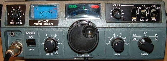
Since 1982 I am in possession of a 2ndhand YAESU FT-7. The 10 W set did well service at home, on holiday and during a UN mission abroad. With a freely suspended home-made FD4 antenna across a Wadi in Lebanon American hams could hardly believe that I was transmit with low power. Furthermore, the receiver is one of the quietest of its kind with low self-noise and the transmitter only draws about 3 A!
Currently there is a revived interest in this rather small and well-built transceiver and modifications are possible to those of interest to you.
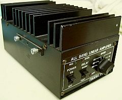
More output is possible (some sets even 25 W) but do not go to extremes. With 10 W output, the transceiver is well protected even with high SWR to the load. Furthermore, this power remains constant with 13.8 V, but also with 15 V or 11 V when the battery needs to be charged. Yaesu has produced a transistor amplifier FL-110 (fig») for the transceiver and this PA is sometimes offered as 2ndhand. A large portion of the device consists of plug-in boards that facilitate modification, repair or installation of your own design. If your circuit don't work just replace the original PCB.
Pretty soon I installed my ideas because in my opinion "improvements" were possible. You recognise the tinkering for some DIY! The set was a long time used as backup and for this article removed from a dusty shelf. I had forgotten why some modifications were installed, hi! After some searching in the mess of my shack, all documents found.
RX RF AMPLIFIER
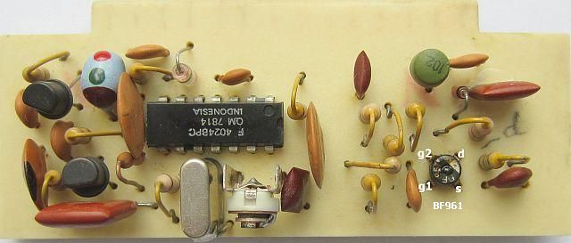
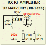
Almost immediately after the purchase (in 1982) the receiver input RF amplifier Q104 (3SK40M) was replaced by a BF900. A modern BF961 will also work in this circuit. Even with the original transistor the gain was too much for the low bands. So the source decoupling capacitor (C113) of was reduced to 100 pF. This value is suitable for 10 m and has sufficient gain for the 40 and 80 m bands without overloading.
CW ROUNDING, STABILISATION
In telegraphy, the envelope of the signal is rather "blocky" causing audible sideband clicks. This can be overcome ("rounding") by the PRE-DRIVE PCB PB-1632:
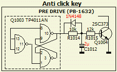
1. A («fig) diode in parallel to R1014 (10 k) and replace capacitor C1012 (0.68 µF) by 2.2 µF or,
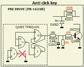
2. Resistor (fig») R1015 (12 k) by 47 k and a 15 k resistor in parallel with C1012 (0.68 µF).
The last method is applied in my FT-7.
LA8AK (SK) discovered that a 9 volt zener diode (D1002) could not stabilise the voltage which stays of 8 - 8.5 V.
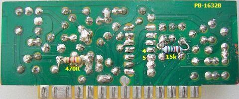
Q1003 (TP4011AN) draws excessive current due to the unused pins (4, 5, 6). One could save about 15 mA by cutting the trace to pin 4.
Apparently YAESU also noted that advice because in my (1980) set pin 4 («fig) was not to ground. I noticed that the voltage across the diode could be improved by paralleling a 470 Ω resistor to R1011 (220 Ω).
ANTI MICROPHONE CLICK
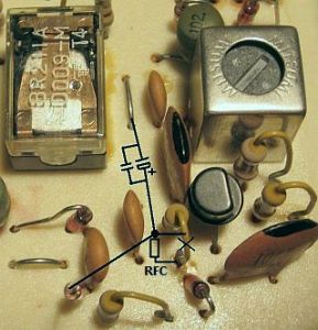
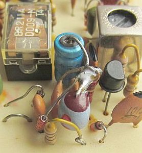
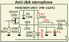
Pressing the PTT causes an annoying click at the other station. This problem was cured in the FT-7B and the update is possible in the FT-7. At the MOD/DEM unit (PB-1624) replace R507 by 2k2 and insert a 220 µH RFC between R507 and D505 (1S1555). Install 1N4148 in series with R507 and decouple with 10 nF and 47 nF.
INCORRECTLY INSTALLED TANTALUM ELCO
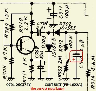
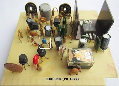
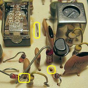
In 1982 I discovered that a tantalum elco was shorted after and few contacts with CW. It appeared that the manufacturer incorrectly installed the component. The negative terminal was grounded in place of the positive terminal. Recently (December 2012) I found the same (exemplary?) errors when repairing another FT-7 and my FT-7B checked.
Don't worry if one does not work CW, but with telegraphy the capacitor always get the wrong polarity and finally blows. The photo shows the correct mounting. Verify your FT-7 and FT-7B for the same problem.
BUFFER AMPLIFIER IN FRONT OF MIXER

The receiver is a single conversion system: a double balanced mixer with Schottky (1SS16) diodes and a 9 MHz IF frequency. The mixer is not loaded with wideband input, therefore a buffer amplifier was mounted. That is pretty simple. The coaxial cable from PB-1631 (pin 2) to PB-1626 (pin 2) is disconnected and the circuit shown was installed.
I used an obsolete P8002 (fig») as amplifier. The FET draws relatively low 15 mA current but the circuit input and output are close to 50 Ω. So you can use a J310 FET with equal result, set R for an Id of 15 mA.
For an improved mixer balance at PCB PB-1631 two 10 nF capacitors were inserted between L201 and the diodes quartet.
Because I had another P8002 as an experiment it was installed in stead of transistor Q201 (2SC535A). To obtain a drain current of about 30 mA, R203 (4.7 k) was removed and R201 (330 Ω) reduced to 56 Ω.
EXTRA BANDPASS FILTER
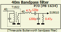
If strong signals occurs on 40 m, one can modify the 40 m input circuit T1922 P/O (PB-1634) to a bandpass filter (BPF). Disconnect the wire from the T1922 and install the extra circuit (fig»).
EXTRA TRIMMER
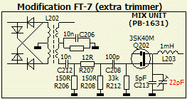
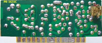
In a FT-7B the PB-1631E unit is equipped with a 20 pF trimmer (TC201) across a 5 pf drain capacitor of Q202 (3SK51-03) providing some resonance of choke L203 (1 mH). In my FT-7 (fig») I arranged it for maximum output on the 10 m band.
MIXER
|
|
|
Just press the FIX switch the next 500 kHz range is available and a LED light.
The last change around the mixer circuit is based on FT-7B's AGC design e.g. FT-7's PB-1631B was modified according to FT-7B's PB-1631D. The second gate is directly connected to terminal 13 by removing R210 (10 k). The white wire in the picture is the direct link. Furthermore, a 1 mH RFC was mounted from terminal 4 to the junction of R215 (100 Ω) and C211 (10 nF). The latter was mounted on the trackside and a 470 Ω resistor replaced R209 (4k7).
In a previous issue a P8002 FET replaced Q201 (2SC535A). The latter is no longer manufactured so my choice was between almost equivalent semiconductors BFW16A, 2N4427 or 2N3866. It was tested with a used BFW16A and only R201 (330 Ω) was given a different value of 56 Ω. This "updated" PCB did well in both FT and FT-7B.
NOISE BLANKER
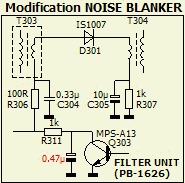
One is not always satisfied with the operation of the noise blanker. After studying the FT-7B diagram showed that the FILTER UNIT (PB-1626) was extended with a 0.47 µF capacitor. Installing the extra capacitance in a FT-7 and proper alignment of the NB UNIT (PB-1627) improves the noise blanker have I experienced.
EXTENDING 10 m BAND
The transceiver was originally equipped with a 43 MHz crystal (X1904) for a range of 28.5 - 29.0 MHz. For another 500 kHz range a different crystal is required. Decades ago the Richter & Co. sold a print design for the entire 10 m range in four stages but at present you have to make your own PCB design. FIX UNIT (PB-1629) must be replaced by the new PCB
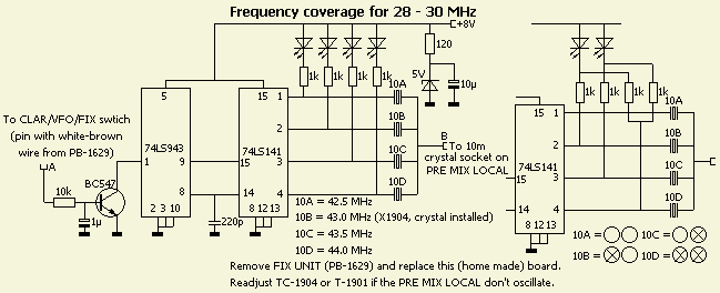
The X1904 crystals is removed from his socket and with the other crystals mounted on the new print board. Terminal A of the circuit is connected the FIX switch on the front panel e.g. the terminal with a brown-white wire.
Indication: the wire leads +8V to terminal 2 of FIX UNIT (PB-1629). Terminal B is connected the hot side of the former X1904 socket. Ifs one of the crystals does not oscillate trimmer TC-1904 at PRE MIX LOCAL PCB should be trimmed or T-1901 adjusted.
In my set I used only two LEDS as indication for the four band segments see the right side of the diagram.
IF FILTER LOAD

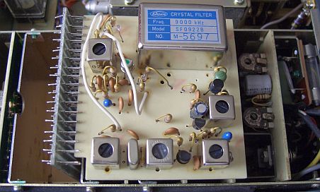
Generally input and output of 9 MHz crystal filters are about 500 Ω. This applies at least for KVG, SHOWA and INRAD filters. So I assume that the Yaesu XF-90A (XF302) need to be loaded with 500 Ω and 470 Ω was installed.
|
|
|
According to the original circuit, the input is coupled to the lower source impedance of Q302 (2SK19GR). Proper load is obtained with a unity gain transistor and a 470 Ω resistor.
During the test I used a BC547 transistor and later replaced a RF type. It turned out that three different RF types were not as good as a BC547B so it was put back. The extra semiconductor was also installed in a FT-7B («fig).
Usually the input and output are also loaded with a 30 pF capacitance. The SF-0922B filter was mounted with two 27 pF capacitors that improves the symmetry of the pass-band.
I have not tested the original XF-90A whether the addition would be an improvement.
DOUBLE SIDEBAND (DSB) CLIPPER
|
Test clipper (fig»). |
|
The above circuit can be extended to a double sideband IF clipper/processor in order to increase average output power. Even better is a SSB IF limiter with a second IF filter, but there is not enough space in FT-7 and FT-7B. I have successfully installed a DSB clipper in a
TS-50S.
Decoupling emitter resistor (470 Ω) increase the receiver gain. To prevent overload the resistor is only decoupled during transmit. Two diodes (1N4148) get 8V via terminal 13, they will conduct and a 220 Ω resistor is grounded through 10 nF. The degree of processing is determined by the setting of the MIC. GAIN knob.
OTHER IF FILTER
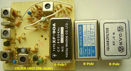
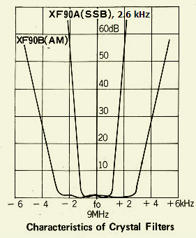
According to the FT-7 manual the (fig») YAESU XF-90A IF filter is an 8-pole 9 MHz/2.6 kHz BW type, but I am not sure about the number of poles.
I was in the possession of two 8-pole crystal filters KVG XF-9B and SHOWA SF-0922B.
The two filters have the same carrier frequencies 8998.5 kHz and 9001.5 kHz as the original filter, a replacement was considered.
|
Test the 9 MHZ/2.2 kHz BW Filter. |
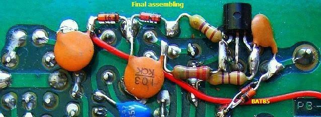
Final assembly. |
Only decouple caps at the trackside. |
Given the limited space at the FILTER UNIT the SHOWA type was most suited to replace the original filter. To test whether it worked well, the filter was temporary installed at the component side of PB-1626. On a crowded 80m band the reception with the narrower type was clearly different from the original filter. The two 27 pF capacitors in parallel with the input and output of the filter improved the symmetry of the band-pass. Carrier frequencies should be adjusted to 8998.5 and 9001.5 kHz.
SSB CARRIER POINT
I did the adjustment as follows:
Tune the transceiver to 14.250 MHz, LSB mode, and connect a 2100 Hz AF signal to the MIC jack.
Close the PTT and adjust the MIKE GAIN or AF signal generator for 8 W output on a wattmeter.
Tune the generator to 300 Hz and adjust the carrier trimmer clockwise for 2 W (which is a difference of 6 dB). Both 2100 HZ and 300 Hz signals should have the same output level!
Eventually repeat the above steps.
Because the SF-0922B filter works satisfactory, it was finally assembled. For sufficient space the two coupling capacitors are soldered to the trackside.
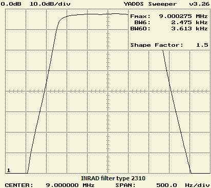
Who wants to spend more money, purchase a 2310 INRAD filter (fig»), which is 2.5 kHz wide, has a nice symmetrical pass-band and should be loaded with 500 Ω.
S-METER

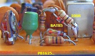
A more realistic S meter indication is obtained by adding a BAT85 Schottky diode and a 100 Ω resistor. Note that R429 and C427 do not have the same value in an FT-7 and FT-7B!
PLUG-IN BOARDS
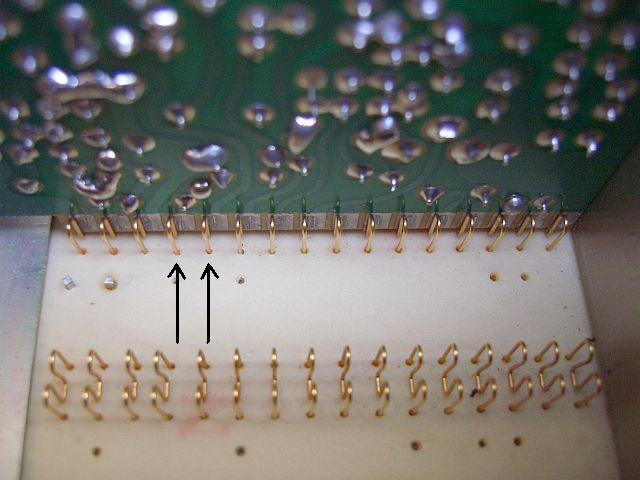
Malfunction or breakdown occurs frequently due to the way the plug-in boards making contact with the motherboard. This is especially noticeable when the set is a long period of time. The tracks are tin-plated contacts and too much tin caused thick PCB tracks. The golden contact springs («fig) on the motherboard have the tendency to slip off the tracks with poor contact or interruption as result.
There are two ways to avoid such disruptions. Remove excess solder with suction litzwire and when inserting a plug-in board be sure that the contact springs are in the middle of the track. In the picture you can see some contact springs are just at the edge of the relevant track. A third measure that has proved is using special contact lubricant.
EXTENSION BOARD
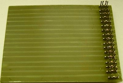
Home made extension board.
|
Extension board made with with a PC connector. |
For measuring or adjusting one need an extension board. This tool was hardly on sale in the last century and therefore I was forced to DIY. The tracks were made with Stanley knife.
The spring contacts of a former PC connector were used for the right board. The boards are somewhat primitive and not pretty, but it works and usually the extenders are not often used.
Moreover, it is worth because last adjusted FT-7B obtained improved reception and has almost identical output on all bands
POWER CONNECTOR
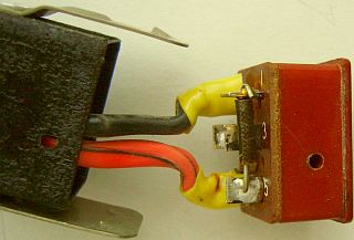
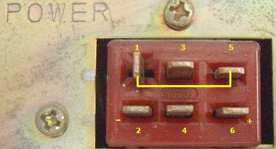
If you purchase an 2ndhand FT-7 the power cable and power plug is not always included.
Sometimes the correct connection of the battery terminals is unknown. Both pictures show the right interconnections.
|
I did not test this idea! |
COUNTER
A FT-7B is a 50 W output successor of the FT-7 and both sets are internally not much different from one another. A digital frequency counter YC-7B for the FT-7B is sometimes for sale. The corresponding accessories plug is missing out on a FT -7.
For someone at his request, I compared the diagrams of respective FT-7 and FT-7B and draw a diagram to update a FT-7 for YC-7B. Note: I did not test the update system and if anyone among the readers will take the trouble to experiment, please post me the result.
![]()