EL519, PL519, 6P45C Grounded Grid Amplifier (FRINEAR 400, 400W PA)
with an aperiodic input circuit.
(FRINEAR 400W-GROUNDED GRID LINEAR in RSGB's RadCom april 1995)
![]() 6-feb-2013 With PE2CJ's PCB of the HV supply.
6-feb-2013 With PE2CJ's PCB of the HV supply.
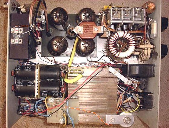
Dimensions: 30×27×15 cm (l×w×h)
INTRODUCTION
The regular visiting of ham flea markets is a money-saving way to obtain parts for a home-brew linear amplifier meeting the requirements of the Telecom authorities. This topic, in Dutch, was originally written about in order to fill some gaps in the Dutch literature on this subject. There are still many radio amateurs (in the Netherlands) with insufficient knowledge of the English language to read the ample source material found in the ARRL and RSGB handbooks, Bill Orr's Radio Handbook and articles in the RSGB's RadCom. Inexperienced hams, in the Netherlands as well as well as in Great Britain, have successfully built this 400 W PA-project, more or less duplicating the here-published design published here. My preceding designs were mostly intended to pep up 10 W home-brew sets. There is, however, a great demand for "simple and cheap" amplifies to be used behind modern 100 W transceivers designed for a 50 Ω load. I therefore based the amplifier described here on a grounded grid amplifier, using cheap and still easily obtainable valves. Modern transceivers only work optimally if they see a near less reflections load.
|
|
|
|
|
|
|
This was the basic circuit, however for safety reasons I do not advocate this design for inexperienced home brewers! |
|
This is taken care of in this circuit. The transceiver is loaded correctly without variable input tuning. After band changing, only two capacitors need to be tuned. The PA has at least an output of 400 Watts on all bands, except 10m and 12 m, where output is down to about 350 Watts. In this circuit sweep-valves are being used. Hams not having much experience with valves may learn much from this project. One day they may want to build an amplifier with a "real" transmitting valve. For them, more in formation has been included.
VALVE CHOICE
EL519, PL519
|
Full size PL519 |
Full size 6P45C |
Full size 6P45C |
I leave it to the pro's to argue about which specific valves should be used in this project; when properly adjusted, every amplifier will behave linearly. In my project I decided upon the well-known (discarded) PL519, used in old CTV sets. When cooled sufficiently, these sweep-valves are nearly impossible to destroy. They especially can withstand high voltages and peak currents. They will even function well with anode voltages far in excess of 2000 Volts, but in order to protect you from extra problems (not to mention the wrath of neighbours and Telecom authorities), I am advising you to apply only with 1000–1600 Volts. The valves may be mounted vertically or horizontally, the choice giving more freedom of layout. While the claimed 400 W could be extracted from three or even two valves, practical reasons dictate a set of four in parallel. The PL509 may be intermixed with the PL519 as their characteristics and filaments (40 V/0.3 A) are the same, but the PL509 has a lower permissible dissipation. EL509 and EL519, which are used much in 27 MHz linears, only differ in filament voltage: 6.3 V/2 A.
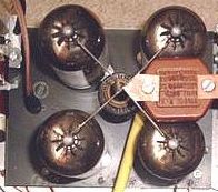
One should reckon with valve diameters differing with different brands: e.g. Valvo's/Philips's having a smaller diameter than Italian and Russian ones. Anyhow, the valve sockets should be spaced at least 6 cm centre to centre for heat-dissipation reasons.
Valves unused for a long time and even new one's, should be first warmed up by having only the filaments on, with the correct voltage, for half an hour. After that, the other electrodes can be connected with the valve drawing its idling (standing) current, without drive for 30 minutes. The internal heating activates a chemical diffusion process, which raises the emission level and also helps restoring good vacuum, thereby diminishing the number of possible "flash overs".
6P45C
A 6P45C is a Russian equivalent of an EL519. (Only I wonder whether it is a penthode or a beam deflection tube). The tube is thicker and often is the envelope made of thicker glass, but there is quite a difference in the mutual production. Note for example in the photos on the anode and the small plates above the anode. According to some users the tube is "stronger" than an EL519, but there are also negative messages.

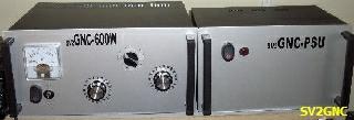
So I think the positive sound comes from users who apparently obtained the better product. SV2GNC build this design with 4 × 6P45C and is very satisfied with the result that is shown in the table.

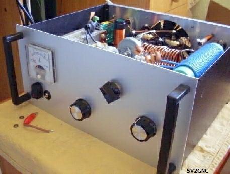
SV2GNC's amplifier, the external anode supply is not shown.
REACTIVATON OR TEST A PL519 (EL519)
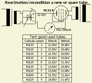
To avoid flashover in a new or a long time unused tube, it is prudent to prepare ("reactivate") it for his task. There are various opinions and solutions how to do it, but with a PL519 it can be relatively simple. A DC of 12.5 to 13.5 V is sufficient for the tube to draw 500 mA as all grids are connected to the anode. Heat the tube 30 minutes with a filament voltage of 40 V/PL519 (6.3 V/EL519). Then supply a "high voltage" of 12 - 15 V and set the voltage to a current of 500 mA. Usually I will not reactivate longer than 30 minutes. Soon you will find out at which voltage a good tube drawn 500 mA, so you have an indication if another tube is better or not.
A WIDEBAND INPUT CIRCUIT
The static input impedance of the cathode in a grounded grid circuit can be calculated if the valve characteristics relating to the specific circuit are known. The dynamic input impedance (during working conditions) is often higher. Furthermore it varies during a SSB transmission because the driver (the transceiver) is delivering power varying between say 0.1 W (the suppressed carrier) and about 100 W. The input- and output impedance of the amplifier are constantly varying and the driver sees a constantly varying load. If the internal controlling system (ALC) cannot handle this, a distorted signal will be generated in the transceiver. With a fast reacting SWR-indicator between TX and PA, one will see a constantly varying SWR. The input impedance of the PL519's in the circuit chosen by me was not known. With an experimental test rig, I have tried to obtain some relevant data. It turned out that these data were different for every amateur band, roughly averaging 17 Ω–27 Ω and with some guessing, I found that for 4 valves in parallel, the average real part was 22 Ω, say 25 Ω.
In most cases a tuned circuit between driver and final stage is recommended. By way of flywheel-action this tuned input-circuit will, to a degree, level out the quite variable input impedance, thereby preserving a reasonable match and thus linearity and output of the driving transceiver. The tuned input circuit also shortens the HF return path between anode and cathode by preventing this HF current to follow the longer path via the transceiver. As modern transceivers have more than sufficient power, the "flattening" of the input impedance may also be obtained by extra loading (swamping) the input-circuit with a resistance or suitable wide band combination, in which excess driving power can be absorbed. This also helps in lowering the HF return-path impedance.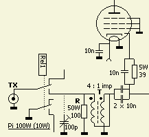
In our case, matching is done with a 4 : 1 HF impedance transformer (fig») which transforms the 25 Ω impedance of the 4 valves to about 100 Ω. By putting a 100 Ω-swamping resistor across it, the driver will see a load with a SWR of less than 1.5. Nearly all transceivers can deliver about 100 W with such an SWR without an antenna tuner. Eventual use a 100 pF trimmer for minimising the input SWR in the 10 m band. Adjustment of the input- and output-circuits must be done with full carrier power (key down) for maximum output power and minimum input SWR.
|
|
|
|
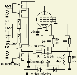
The transformer («fig) is wound on a ferrite rod from an old MF radio. A 5 cm piece of 1 cm diameter will do, longer is OK. With enamelled wire of 14–19 SWG, 9 close bifilar turns are made on a 9.5 mm drill bit and then slipped onto the ferrite rod. This is a safe method as the ferrite is quite fragile. The two inner wire ends must now be soldered together; this junction goes via 2 × 10 nF to the common junction of the 39 Ω cathode resistors. The two outer wire ends will go, via capacitors, respectively to earth and, with a piece of coax cable, to the input relay
This (right picture) alternative simpler resistor input circuit has a higher SWR on 10–40 m and reduced output on 10 m, however this should not be a problem with a modern transmitter with a built-in antenna tuner.
IDLE CURRENT ADJUSTMENT
When using valves in parallel, we have to consider the individual differences. With collective bias, individual-resting currents will differ. Even if the idle currents are made equal, the HF-amplification factors are not. In our bare-bones circuit, an individual adjustment was considered, but left in favour of a simpler system, based upon DC-feedback during excitation.

This is done with by-passed 39 Ω resistors in the individual cathode leads; a valve drawing more current will bias itself more and therefore reduce its amplification. The resistors will also partly determine input-impedance. Their value can be lowered (down to 10 Ω), to increase the output. However, the SWR will be higher on some bands, causing a transceiver without built-in antenna tuner to resolutely settle back. The older, valves transceivers with pi output tuning do not have this problem.
|
|
|
|
Collective and individual bias. |
|
|
Bias per tube with variable transistor "zener diodes". |
The value of the collective bias is adjusted with a string of 3–10 diodes in series. Short circuit one of more for a standing current of about 20–25 mA per valve, i.e. 80–100 mA in total for 4 valves. When using this simple bias circuit, it is advised not to wait too long with speaking after pushing the PTT button, in order to let the valves draw standing current for only a short moment. The reason for this prudence is the possibility that the individual currents deviates so much, that one or two will draw much more current and dissipate excessively. In this way, the valves will only conduct when the PTT is activated. As a rule, the individual products of standing current and anode voltage should stay below the maximum dissipation of 35 W per valve. Assuming a 10 % spread in standing currents the total dissipation, while sending without drive, will be about 130 W. Eventually use the individual bias system with a string of diodes in series with each cathode.
FILAMENTS
|
Filaments and capacitor in series connected to mains. |
|
|
Each PL519 filament requires 40 VAC/0.3 A. In our circuit, the four filaments may be fed in series; with a capacitor of 5.6–6 μF/250 VAC added in series. The string may be connected directly to the 230 VAC mains. If the chassis of the PA is grounded through the mains cable this method is acceptable, with the added benefit of a gradually heating up (soft start) of the filaments, i.e. without the thermal shock incurred by transformer feed. Because the cathodes are not at HF earth level, the filaments are by-passed to earth with capacitors.
The right figure is an example for the calculation of the capacitor in series with 0.3 A filaments.
CATHODE
Because of the grounded grid circuit, the cathodes must be HF-isolated from earth with an RFC.
GRIDS

In this circuit all grids are at earth potential. At each valve socket, all six grid-pins must connected to each other and be grounded via one point to a common spot (chassis, print-board copper side) with short connections of thick wire or ribbon strip (low inductance). The grids are negatively biased with respect to the cathode through the forward voltage drop of the string of diodes, which positively biases the cathodes with respect to earth. In triode circuits, contrary to tetrode or penthode circuits, the bias voltage required for a given anode current greatly depend on the anode voltage: the higher the anode voltage, the higher the required negative grid bias.
ANODE
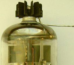

The anode connection is at the top of the PL519. Top clips are difficult to obtain, but transistor-cooling clips are a good alternative. These may have to be bent a little for a good fit. They are made of blackened copper. The contact area should be scraped bright as well as the area where the connecting lead is to be soldered. The cooling clip keeps the temperature of the top within reasonable limits at high dissipation. With a good design and neat mechanical layout, there is no need for the usual parasite killers in the anode leads to stop parasitic oscillations.
NODE CHOKE
About plate chokes, varying stories circulate. However, least problems arise with one-layer chokes. Because of the dissipation and closeness of the power valves, a heat-resistant coil former is a must: the heat and intense IR-radiation of a power valve at maximum dissipation can make phenol board at 2 cm distance burst out in flames!
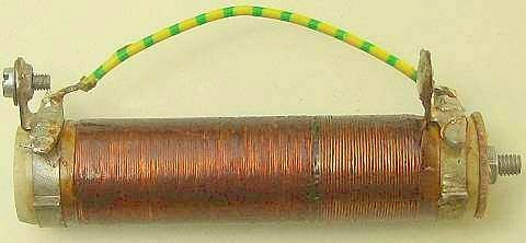
A sturdy ceramic wire-wound resistor, with its resistance wire removed, will make a good former. A diameter of about 2 cm and a length of 10 cm is satisfactory. Closely wind the former with one layer of 25–28 SWG enamelled wires over a length of 5–10 cm. In most cases its inductance is sufficient, even at a lowest frequency of 3.5 MHz. To test for series-resonance, short both ends together («fig) and (with a GDO) checks for resonance in the amateur bands. If there are none, you are lucky. If there are, try to shift them by removing or adding some turns. Another solution is to remove 1 cm of the windings and start again, leaving a gap of 1 cm between windings; then check again. My favourite choke has a diameter of 2–2.2 cm, is closely wound over a length of 5 cm with one layer of 28 swg enamelled wire, has an inductance of about 180 μH and will serve for all bands. The wire may seem too thin for some currents, but in all my experiments it never burnt through. The wirewound resistor (10–50 ?) between +HT and the choke will limit the damage from "flash-over", caused by a momentary short in a valve, to the fuse and (often) the limit-resistor itself. Replacing them is much cheaper than replacing valves.
ANODE IMPEDANCE
Normally the anode- or output -impedance is known or can be calculated, or can be taken from a graph. However, hams are in the habit of (miss) using valves in other than normal ways, so available data don't apply. In the past I have built linear amplifiers in a test circuit, following published schematics or design formulae and copying given values of components. After a while however, one will get an itch to experiment with this or that. Quite often in the following years, output was raised after tinkering with the output circuit. With simple means, the results were measured and tabulated, after which I tried to find a matching formula. I found my results to differ from the formulae and tables as found in handbooks of the years '60. In all probability, pure class B or C was then adhered to. Adjustment according to my "found" formula is a good directive for home-brewing amps that are meant for CW and SSB. The anode-impedance of an unknown amplifier's final stage with one or more valves, according to my findings is:
|
Za = Va ÷ (1.87 × Ia), in which: |
|
Za = the (common) anode (or plate-)impedance, (in Ohms), |
|
Ia = the (total) anode current at max. power, (in Amperes), |
|
Va = the applied anode voltage, (in Volts). |
One may dispute the value of the last decimal, but please consider that it is the average result of many experiments. As it is, the formulae worked very satisfactory for me.
CALCULATION OF PI FILTER
|
With my formula we find as a suitable anode load (Ra) for |
Va = 1100 V/0.8 A: Ra = 1100 ÷ (1.87 × 0.8) = 735 Ω. |
|
The anode-circuit must transfer energy and the circulating current amplification factor Q helps to suppress the generated higher harmonics. A loaded-circuit Q of 10–12 will meet most requirements regarding efficiency, suppression of harmonics and practical values of C and L. If we assume for the 80 m band |
Q = 5, |
|
then the loaded circuit-impedance becomes |
Za = Ra ÷ Q = 735 ÷ 5 = 147 Ω. |
|
The tuning-C (=Ct) is mostly responsible for circuit-resonance, which occurs at the frequency for which |
Zct = 147 Ω. |
|
We recalculate to obtain pF's: |
Ct = 106 ÷ 2πfZct, in resp. pF, MHz and Ω. |
|
For 3.5 MHz this becomes: |
Ct = 106 ÷ (2π × 3.5 × 147) = 309 pF. |
|
This includes anode capacitance, wiring capacitance and stray capacitance! The circuit transforms the anode-impedance |
735 Ω down to 50 Ω, |
|
giving an impedance ratio of |
735 ÷ 50 = 14.7 |
|
and a capacitance ratio of |
√14.7 = 3.83. |
|
The second C, normally called loading-C (=CL), has a value of |
309 (pF) × 3.83 = 1183 pF. |
|
Now we calculate the value of L: Across the coil L is the series combination of |
Ra + Rload = 735 + 50 = 785 Ω. |
|
The loaded coil with a Q of 5 will, at resonance, see a resistance of: |
Rs = 785 ÷ 5 = 157 Ω. |
|
Calculating for inductance gives: |
L = Rs ÷ 2πf = 157 ÷ (2π × 3.5) = 7.14 µH. |
It can be argued that the calculations with Za = Va ÷ (1.87 × Ia) formula could be more exact. Just ask yourself what value you should assume for the added capacitance, caused by valve, wiring and stray capacitance's...this uncertainty is much higher than the one caused by a somewhat simpler calculation.
PI-FILTER
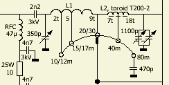
The pi-filter in the output circuit is a compromise. At the lower bands the Q is lower (see calculation), in order to restrict the size and value of the tune- and load-capacitors. At the highest band, the tuning-C cannot be made small enough because of the high capacity of the anode circuit. It consists of the combined anode capacities of all valves, about 10–15 pF for the tuning capacitor's minimum and about 4–8 pF for stray capacity. At about 22 pF anode capacity for one sweep valve, our total minimum tuning capacity raises the loaded Q at 10 m and perhaps even at 15 m. This results in lower efficiency through higher circulating current losses and a lowered output at the antenna terminal. However, the situation is not that bad. We may consider the anode- and stray capacity as the C of a separate L-network in which the lead from anode clip to tuning-C acts as an inductance. We then see a combined L- and PI-network. Assuming that the anode lead is about 12 cm long (about 0.06 μH --> reactance = 12 Ω at 30 MHz), we may obtain (by the necessary parallel-to-series conversion) an equivalent driving-point impedance which may be about 30 % lower, and an associated shunt reactance which is also much lower. The net result of this analysis can be an explanation for the still reasonable circuit efficiency in the 10 m and 15 m bands.
CAPACITORS
|
Vintage valve LW/MW radio type variable capacitors. |

The anode-voltage and -impedance are relatively low, as is the RF voltage across the tuning-C, so this variable capacitor might be an old valve LW/MW radio type (photo) with a reasonably (0.6-0.8 mm) wide spacing between the plates. At 400 Watts and a 50 Ohms load, the loading-C has still only 200 V peak across it, so here the spacing could be even less. However, when miss tuning with full power, the voltage may rise to several times this value and therefore 500 V should be a safer margin. In practice the old BC-types or newer small types (fig») with 3 or 4 sections are very suitable.
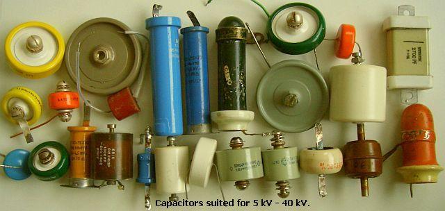
The value of the coupling capacitor between anode and tank-(output) circuit is not at all critical. Any value of 1000 pF and over will suffice.
It is imperative, however, to use high voltage types (disk- or button types are fine) of 3 kV working or more. Be careful with HV capacitors from TV's; they were not intended to carry high RF currents.
COILS
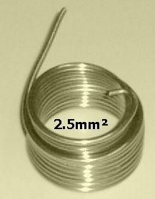
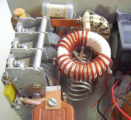
The coil L1 for the 10–30 m band is made of 2.5 mm² or 2 mmØ tinned solid copper wire («fig). It has 9 turns with an inner diameter of 25 mm and a length of about 60 mm. This wire being tinned, I believe the high skin-resistance helps in preventing parasites. Adjust for maximal power at 28.5 MHz by compressing or elongating the 10 m part of the coil and/or repositioning the tap.
Always first disconnect the HT and discharge the electrolytic capacitors with a 220 Ω/10 W resistor.
Keep one hand in your pocket! With these experiments, safety glasses are advised, because resistors, capacitors and fuses sometimes disintegrate spectacularly.
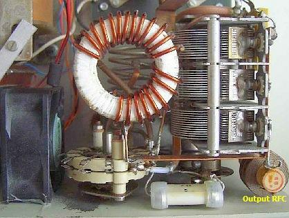
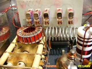
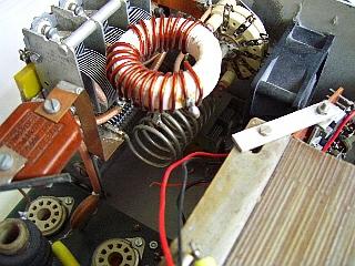
The 40 & 80 m coil L2 («fig) is wound on an Amidon T200-2 toroid core. This was done in order to limit the overall dimensions of the amplifier (l × w × h = 30 × 27 × 15 cm). A toroid, self-shielding because of its low external field, facilitates compact construction. Before winding, several layers of Teflon plumbing tape (fig») must be applied to the core, to insulate it from the coil-windings. Another method of insulation is to cement two flat isolating washers (e.g. made from bare glass fibre board) on each side of the bare core. Apply a small quantity of super glue, possibly only a few drops, around the sides of the core. Work swiftly; the glue hardens quickly. The glue prevents the washers from moving out of alignment while the core is being prepared for winding.
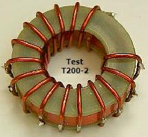
For a T200-2 core, the inner diameter should be 28 mm diameter and the outer diameter 55 mm. With this last construction it might be even possible to use bare copper wire for the two windings, which face each other, of respectively 7 and 11 turns of 14–19 SWG enamelled wire.
At the output end of the pi-circuit, an RF-choke between antenna-terminal and earth ensures a low-resistance DC-path, as a safety measure in the event of a short between the anode and the output-circuit. The Telecom authorities also require it. When the anode voltage is shorted to the output, without a DC-path to earth for blowing the HT fuse (the wire-wound resistor in the anode-circuit will curtail the flaming arc across the blown fuse), the antenna cable and antenna will become death traps. An adequate choke is a short ferrite rod with 30–50 turns of 25 SWG enamelled wire. Check it with a GDO for absence of series-resonance in any amateur band
.
HT POWER SUPPLY
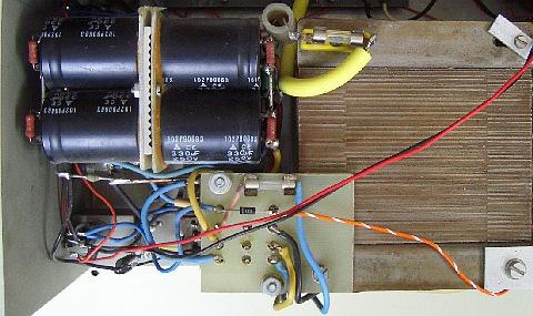
At present it is not so easy to obtain suitable high-voltage transformers. Using a ≥ 600 VA high-power isolation transformer solves the problem. With a 3-way step-up quadrupling circuit, the voltage obtained is sufficient.
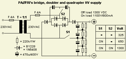
This is («fig) a circuit, which with 6 capacitors, 6 diodes and 2 switches, will rectify, rectify and double or quadruple the 230 VAC. I never saw this circuit elsewhere, so I presume I am its inventor... If you don't want the feature of tuning up with lowered voltage (which prevents problems), the switches may be left out and the appropriate connections made. The voltage after quadrupling will average 1150 V during SSB transmission and about 1000 V with a constant carrier.
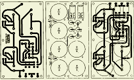
PE2CJ designed a (fig») PCB for this power supply. According to the truth table S1 should not be "off" if S2 is "on". Therefore he is used a S1 to link S2. If (accidentally) S1 turns off, relay S2 still activates contacts of S1 and S2. Click on HV supply for his PDF file.

Series connection of small modern electrolytic caps made for switch-mode power supplies with large capacity and high voltage rating (from 220 µF/400 V to 470 μF/500 V) will give adequate smoothing and regulation even during modulation peaks. They should be individually bridged by equalising resistors of 100 kΩ (2 W). For safety reasons and adequate cooling, it is better to have two 220 kΩ or three 330 kΩ resistors in parallel instead of one 100 kΩ.
The nominally 400 W output (350–500 W) is based on the quadrupled supply schematic. As mentioned before, any voltage between 1000 and 1600 V is usable and will determine to a large degree the maximal power output, keeping in mind the proper idle current(s). Too low an idle current will make the PA harder to drive and will worsen IMD-figures. Too high a standing current may cause overdrive, lower efficiency and excessive dissipation when not modulating.
There is no soft-start delay in the power supply as I presumed the step-up circuit and the internal resistance's in the transformer to be high enough to limit the inrush current.

Electrolytic capacitors, which have not been used for a long time, should have their dielectric reformed first. This also holds for new ones, as the date of manufacture is seldom known. Reforming is done by charging the individual electrolytic caps through a diode and 10–50 kΩ/10 W resistor with a 200–300 VAC supply. If the leakage current and voltage are stabilised (may take 30 minutes), the supply voltage can be raised to the intended working voltage, which should be lower than the nominal one. After testing, the electrolytic cap should be discharged through a resistor. Normally, I use a 220 Ω/10 W resistor.
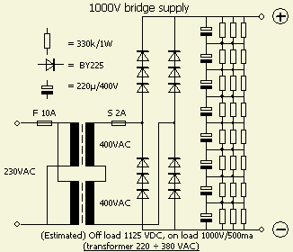
A rectifying and doubling supply with two 220 ÷ 380 VAC transformers (fig»).
CONSTRUCTION
The pictures give an idea of the layout of the important components in the experimental amplifier. In constructing the cabinets, I have learned to first make the holes for the valve sockets in a sheet of single-sided print-board and wire it completely, with sockets on the bare side and the resistors, decoupling caps, grounding strips and the 4 : 1-transformer on the copper side. In this way, the earth-return connections will be shortest. With regard to HF, the print board should be mounted insulated from the chassis with insulating spacers. In this way the board has only HF connections with the chassis at two points: through the input coax braid and at the place where the tuning C of the output circuit is grounded. By doing so, we best approximate "one-point" ground. For maximal power in the 10 m band, use short connections. Strips made from 10 mm wide copper foil, or the flattened braid from RG 213 coax are best; lay-out and construction should follow VHF techniques. Heater leads and cathode-bias is led through 1 nF feed-through capacitors soldered in the print board. Tuning and loading C should be insulated from the chassis. Mounting them on a metal apron, with short connections to the print board and the tank coil, may work equally well.
|
|
|
|
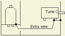
This "one-point-ground" is my improved system, which use a (short) coax cable of which the outer serves as ground strap. I consider it not necessary, owing to the wide tuning range of the pi circuit, to have separate taps for the WARC-bands. Power on these bands is also 400 W.
The T/R-relay has two sets of contacts and is controlled by the transceiver via a screened lead.
The non-inductive 100 Ω/50 W resistance is made up from two 50 Ω/25 W "HF"chip resistors in series.
|
|
Chip" non inductive resistor L to R: 50 ?/250 W, 50 ?/150 W, 150 ?/30 W, 50 ?/25 W |
|
Both are mounted on a cooling block in the vicinity of the blower. At 400 W output the valves would also dissipate nearly 400 W (intermittently). As has been stressed before, the valves should be cooled very well in order not to fail prematurely or have a short life expectancy. Expelling hot air, or blowing in fresh air may do cooling. Both methods have been used in my compact test rig and the first method seems best. In first tests, an 8 × 8 cm computer fan at the back expelled the warm air.
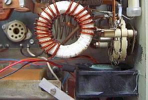
In later tests a second fan (fig») was mounted in the centre of the front, drawing in air from the side, which blows air across the valves and over the HF swamping resistors.
Valves should be mounted far enough from reflecting metal surfaces, like shiny aluminium partitions. These should be coated with a dull black heat-resistant paint. Try to mount the valves (EL519/PL519) in such a way that the welding seams of the anodes do not point at each other. This is to prevent too intense IR back-reflection.
Extension to the 160 m band should pose no problems for the experienced ham. For others it will be a challenge to sort out and realise the circuit-dimensions.
ADJUSTMENT OF THE LINEAR
After having (re) checked the newly built linear, the transceiver, a dummy-load and a power meter are connected. Don't forget the control lead for the relay! If, after applying power, the linear does not burst into self-oscillation, as evidenced by any RF output, you probably did everything right. Now push the PTT-switch (in SSB mode but without speaking into the mic.) then one at a time, short as many of diodes in the cathode diode string as it takes to obtain the desired anode idling current.
Warning: be sure the power is off and the HT electrolytic caps discharged before touching any internal wiring!
With about 10 W drive and beginning with the 80 m band, tune the output-circuit for maximum power. Repeat the procedure, alternating between loading C and tuning C, till maximum power is reached. NB Whistling in the mike will not give a steady signal, a carrier (CW or FM) is necessary for repeatability.
Now raise the drive level to 100 W and repeat. Let the PA cool for at least 30 seconds after every 30 seconds of transmitting, to keep the valves healthy. Off-resonance, hefty currents can flow through the valves! If possible, proceed initially with lowered supply voltage. All now seems adjusted optimally but pay attention: lower the capacitance of the loading C until the needle of the power meter falls back 2 to 3 needle thickness; now re-adjust the tuning C for maximal power. Only after this last adjustment is full linearity achieved. Record capacitor settings before proceeding to the next frequency and/or antenna.
VARIOUS TIPS
The use of panel meters for the various voltages and currents depends on personal choice. I only meter the anode current (in the minus-line of the power supply), because my linear is stable and in normal use, knowing other values is not deemed necessary. An external SWR/power meter is connected permanently for supervision.
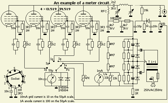
However I got several demands for a simple meter circuit and this is an example. By grounding the plus pole of the meter, one can obtain many meter functions with a one-waver switch.
For safety reasons in my test amplifier, the two switches for doubling or quadrupling the voltage have been replaced by relays, which are controlled by push buttons on the front panel.
HF decoupling of all rectifying diodes with 1 nf/3 kV in parallel is recommended. There are special long fuses for high voltages, but in this design, the standard fast 250 VAC ones have been used. Thanks to the extra current limiting resistor in the anode circuit, I never had problems with these fuses in all my amplifier projects. Keep in mind that non-professional fuses will blow, as a rule, at 2 times the nominal current.
It is safer to feed the heaters of PL519's in parallel with a 42 V transformer and inserting a resistor of 6.8 Ω/1 W in series with each filament, to eliminate the excess 2 volts. The named resistors in the broad-banded input-circuit can only stand 100 W maximum during an SSB- or CW-transmission. Don't overload them and restrict tuning with full power.
A mains filter is built-in to prevent or reduce a possible cause of TVI and BCI.
At higher anode voltages, the anode-current wills not rise much, but output power will, if the pi-circuit is re-adjusted [according to the V ÷ (1.87 × I) formula]. Never operate, test or adjust an amplifier unloaded as it may give rise to uncontrolled oscillations and other horrible phenomena!
In parting, I hope you will operate your product with pride. Still far too few amateurs can say: "I built it myself".
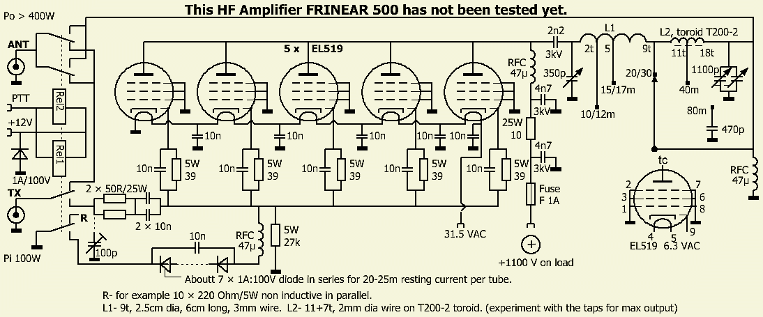
5 × EL519
Some CB/27MHz amplifiers are equipped with 5 × EL519 tubes. One tube serves as a preamplifier to drive the four other tubes. The filaments are connected in series because the transformer supplies a voltage of 31.5 V/2 Amp. Based on the content of these CB PAs, this design was drawn at the time, but is still not actually built and tested.
Maybe this can be the start for someone to experiment with five tubes. Only the power on the 10 m band will be much less then on the lower HF bands.
HOME BREWED AMPLIFIER BY OTHER HAMS
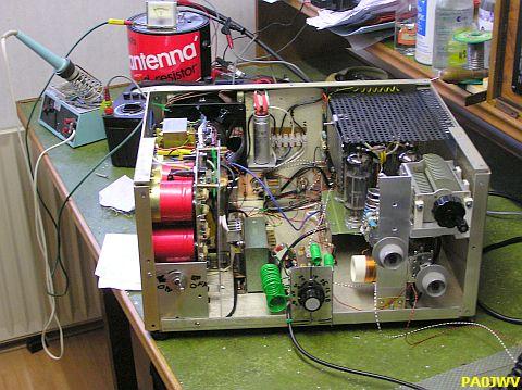
See the next examples made by PA0GS0, PA3AGF, PA3CLL, PA3FTP, PE1ANN, PE2B and ON5DRE
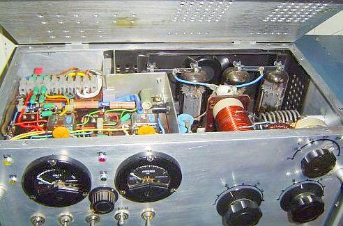
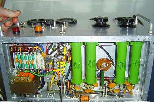
Made by PAØGSO.
The green coloured tubes are four series & paralleled 100 Ω resistors for the 100 Ω input "dummy load".
|
Made by PA3FTP |
ON5DRE, click too enlarges.
PA3CLL, click to enlarges
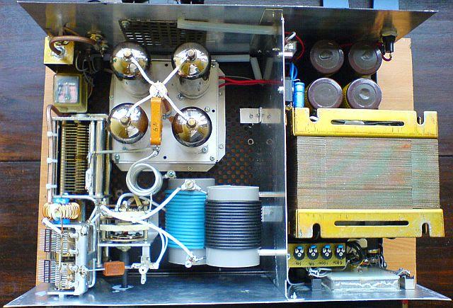
PE2B's home brewed amplifier.
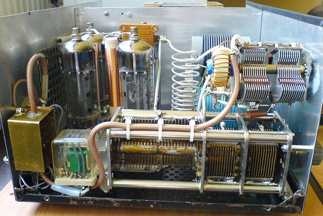
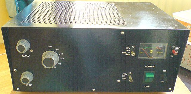
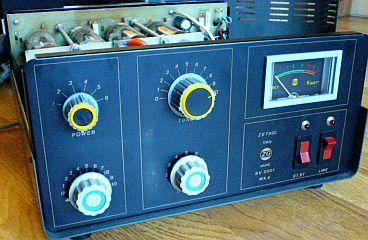
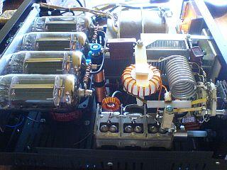
PE2B's rebuild ZETAGI BV2001.
|
PE1ANV's shack
Indeed the PA on the desk is home made! |
|

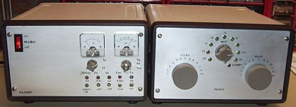
PA3AGF gained the first prize in a home brew contest.
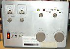

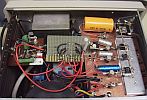
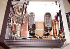

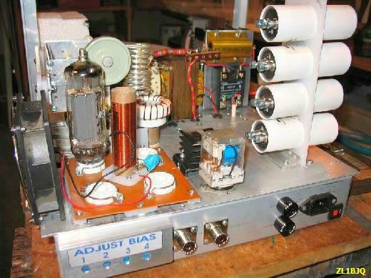

ZL1BJQ's amplifier under construction.
PA3I's QSK VERSION
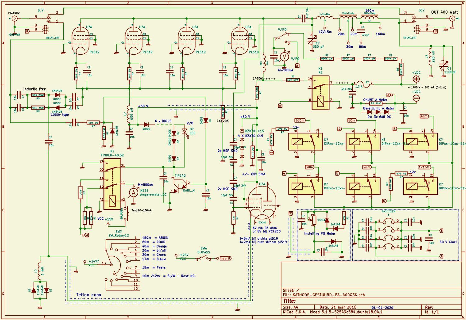
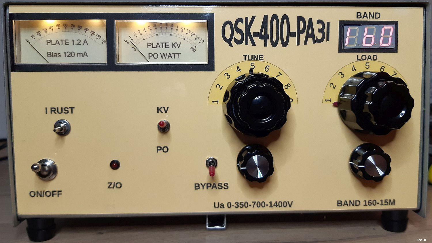
![]()