PL 519 400W QSK LINEAR
(HIHG-POWER "FRINEAR" LINEAR RSGB's RadCom Feb 1990, also published in ELECTRON (NL) May 1990 page 243 - 245).
![]() 14-jan -2018 Couple cap to PCF200 increased to 7-10 pF.
14-jan -2018 Couple cap to PCF200 increased to 7-10 pF.
Darlington transistor type like BD645, 647, 649 and 651.
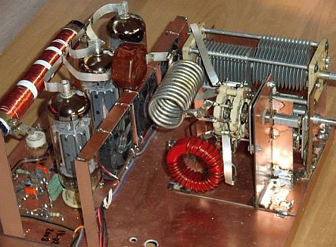
This amplifier with three PL519 valves and without any relay is capable of providing a full legal SSB output of about 400 W. While the circuit diagram provided the necessary basic information, care must be taken to use suitably rated components, adequate fan cooling, etc. Remember always that this is a high-power amplifier with potentially lethal voltages.
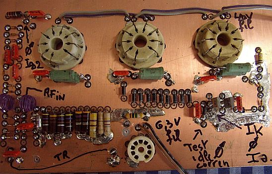
The 82 Ω cathode resistors provide negative feedback and helps to equalise the valve currents.
On the 7 – 28 MHz bands it is essential to tune out the input capacitance of the paralleled PL519's with a input circuit in order to obtain a low SWR and sufficient drive power (7 – 10 W across 50 Ω).
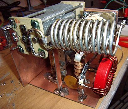
The ouput pi network uses smaller components and values than those commonly specified for the 3.5/7 MHz bands, but has proved quite adequate with regard to efficiency, linearity and harmonic suppression.
In case of overdriving or instability, some of the 1N4148 diodes in the screen grid circuit will "blow" and the amplifier ceases to function.
I have modified (fig») the old-style grounded anode one-valve triode electronic transmit-receive switch. I used a triode connected PCF200 incorporated with a four-diode circuit in series with the cathode to provide additional isolation for the receiver in the transmit mode. So creating extra blocking between input and output of the amplifier.
The pi output circuit is an additional input resonant circuit for the receiver in the receive mode. The "triode" is used as cathode-follower stage to couple between the tuned (tank) circuit and the receiver. In this simple electronic switch (fig») the valve is biased (-Ug1) during transmission periods by rectified grid current, (5 pf & 1 M?) and limited power is fed to the receiver to injure its input circuit.
On-air reports received using this amplifier are proving encouraging and a two-tone test show a correct envelope pattern.
The PSU (see HV 1300V) uses voltage-quadrupling to avoid the need for a high-power transformer but for safety includes a high-power 1:1 isolating transformer. This arrangement provides roughly 1250 V under no-load conditions and a average of some 800 mA at 1150 V in processed-speech SSB or CW modes.
I have experimented with different systems to generate the screen grid voltage. One of the other systems you see below.
|
|
|
ON6JWF's AMPLIFIER

PA3i's QSK VERSION
![]()
![]()