PA0FRI's ACTIVE LOOP ANTENNA
Experiments with various amplifiers.
Version 05-May-2022
PCB's are available again for €12.50 each including power supply print and white toroid core.
Ask about shipping costs. Please state your name and address when transferring.
We thought that the design had been extensively tested by now, but it turns out that in my loop a choke balun between antenna and amplifier greatly reduces a certain type of interference. A station with the loop is therefore better to copy than with the wire antenna. A possible declaration is that an interference signal via PCB's copper clad enters into the receiver.
PD0EEA found that a capacitor parallel to the input of the amplier improved reception at 80 m and below. I have also established the latter.
As a result, we are testing this still experimental design.
A preliminary conclusion is that the parallel capacitance should be 100 - 150 pF. At present I used 120 pF. Incidentally, PD0EEA has already taken into account with the design of the PCB that an additional capacitance may be added. The coupling capacitors of 1 nF to the bases have been increased to 1 µF.

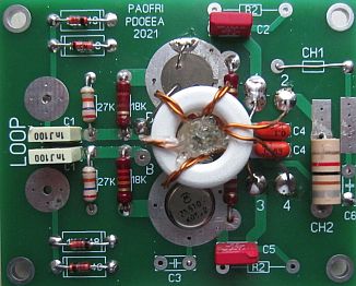
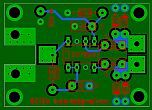
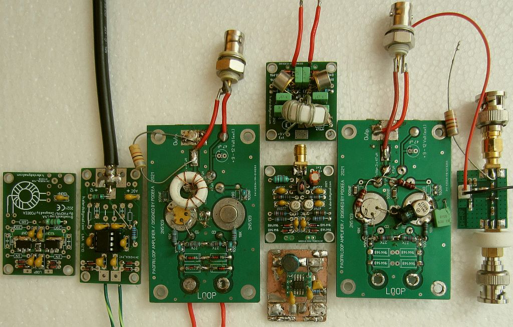
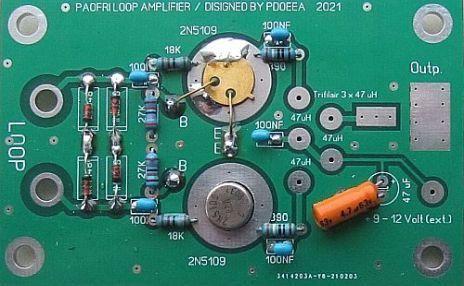
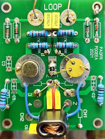
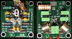
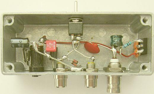
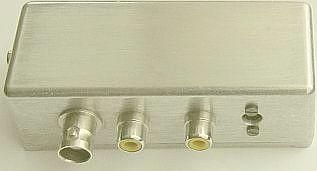
For a nice finish of the working circuit, the spacious PCB design of PD0EEA was used.
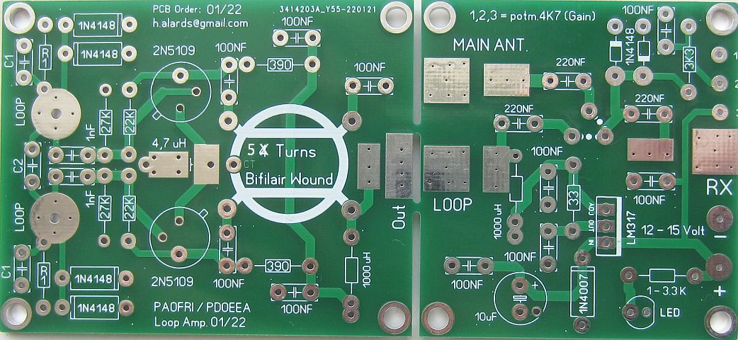
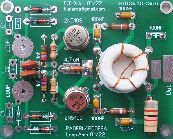
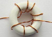
These are more compact PCBs according to the schematic above. The white toroidal core is supplied with the print. The print shows 4 turns bifilar, must be bifilar and 5 turns.
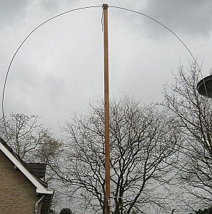
As transmitting antenna for the spectrum analyzer, an equally large 120 cm diameter loop was used.
The descending gain is quite similar to that of the receiver in conventional HF transceivers.
All loop antenna amplifiers shown in this article work well. The best is the November 12 design. By reducing the collector-base resistance from 33k to 22k, the sensitivity improved slightly. The loop with amplifier showed a dip between 2.5 - 3.5 MHz. By reducing the base coupling capacitor to 1nF, the loop is brought into resonance in that range, causing the dip to decrease. The supply voltage is not critical, but with about 14 Volts it is optimal. A constant current source is used to limit the current during experiments in the event of a possible short circuit.
During his experiments with all kinds of amplifiers for an active loop antenna, PD0EEA came up with the idea to also use an MC1350 as an amplifier. He was dealing with a balanced output and I found an opportunity to save some components with an asymmetrical or coaxial output.
Readers wonder why a better matching was not used, for example by installing transformers on ouput and/or input, so that at least 6 dB or more gain can be achieved. That is not necessary with my IC7300. When switching from an antenna tuner with a connected 2 × 16.55 m dipole to the loop antenna, nothing needs to be changed in the setting of the transceiver. With more signal from the loop antenna, the attenuator must be switched on or the RF gain must be reduced. In practice, the signals from both antennas are almost the same and depending on the band or time, the loop can be slightly stronger or the dipole gives slightly more signal.
These are other options.
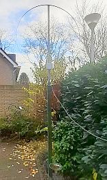
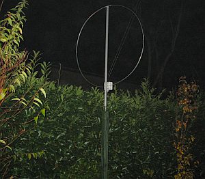
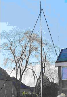
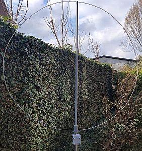
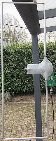
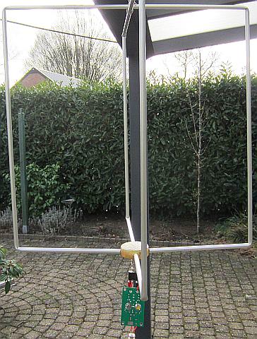
The antenna is mounted on a 1.70 m high wooden pole in the backyard about 6 m from the house. The amplifier's own noise is then lower than the background noise.
The power supply is a constant current source of 18 mA. This was accepted because during experiments it regularly happened that the supply voltage was short-circuited and now this is limited to 18 mA.
With such a simple design one can have doubts about whether it works. This can be found out by assembling it in an electrically responsible way and then testing it.
Too short-sighted is the following theoretical comment: "Someone told me that thing was hopelessly unstable and suffered from overdrive and oscillations. Nice but oversimplified circuit. IF it works at all, it is probably bursting with local man made noise, IMD, and oscillations. Further the S-meter reading in the RX says nothing about the actual strength ratios. Nice to earn quickly as a kit." Sic!
Production of MC1350P is currently by or on behalf of ON Semiconductor. I ordered 10 pieces from China and compared them with a pair of original MOTOROLA MC1350P I still had in stock. No difference could be identified. Further the online shop of https://www.funkamateur.de/ has them in stock.
A recent experiment.
|
|
|
Loaded with 50 Ohms (receiver input) the gain is straight from 1.8 MHz to 70 MHz.
Both amplifiers were connected in parallel to the loop to switch the coaxial cable from one amplifier to the other as quickly as possible. This allowed the signal strength for both systems to remain as identical as possible. It can be seen that the difference between them is minimal. I therefore prefer the simplest design, but the choice is yours.
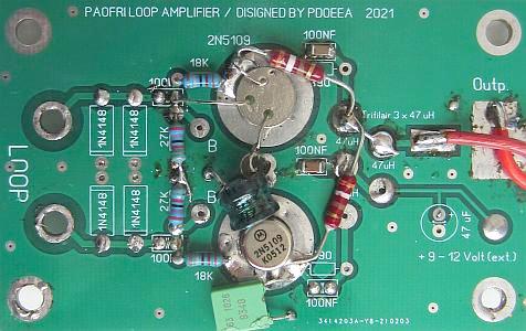
Test with PA0FRI's design.

INTRODUCTION
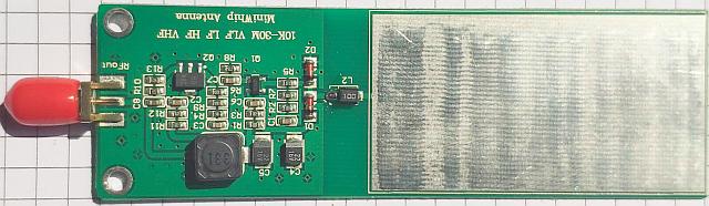
 The widely circulating active "(mini) whip" antennas performs well in the open field, but in a densely populated residential area the system picks up much less signal. The reception performance is also much less during the day than in the evening and/or night. That is the experience of PD0EEA, when he tested it with two purchased mini whip's. A loop antenna, on the other hand, receives better in a densely populated residential area and can minimize any interference by rotating the loop. Given these advantages, a Loop antenna is the best choice.
The experience gained with PA3GZK's active loop antenna has led to experiments with discrete components to test other preamplifiers.
It has become a project together with PD0EEA. We exchange the results of tests, he designs the PCBs, has them produced and takes the necessary measurements. The intention was to design a system that works as simple as possible and be a KISS project that works well with little hassle.
For the time being, two systems will become available with which one can experiment as desired. To this end, a universal print design has been made, which, once produced, can be ordered from PD0EEA. On request he can also supply a complete antenna system consisting of the loop antenna including antenna amplifier.
PD0EEA is still experimenting with amplifiers and if that yields an equally good or better result, a separate article will follow.
|
Many amplifiers have been made and tested, with 1 or 2 transistors, with 4 transistors, a balance circuit or a single circuit.
|
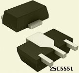
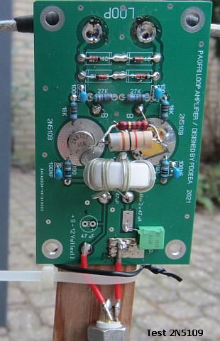
2N5109
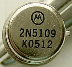
I still had 2N3866's, but another type (2N3904, BFG541, BFG591?) might be better suited. It also turns out that it works well with an obsolete original RCA 2N5109. A (clone?) 2N5109 is currently produced in CHina. A dozen have been ordered to investigate whether they are equivalent to the RCA's. From a number of "RCA" 2N5109's no. K0512 made in Korea, 4 ones were chosen at random and compared with each other: 2 × hFE 174, 1 × hFE 122 and 1 × hFE 94. A big difference between the first and the last!
With my order for 25 × 2N5109/K0512, the measurement result was:
At a later stage, 10 more were ordered. Instead of K0512, K0342 were delivered. Of one transitor the collector wire was missing.
PA3GZK made two identical loops with 2N5109 and 2N3019 and there was no difference between the two systems. So a 2N3019 can be used instead of a 2N5109.
A GOOD PERFORMING SYSTEM
The supply voltage is not critical, it works from 5 to 16 V, but we did tests with 13.8 Volt and that voltage is usually present in everyone's shack.

Various PCBs have been designed during the test period.
This universal PCB has been updated to the latest modifications and are currently being manufactured.
You can use it for experiments or make the above circuit.
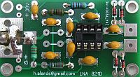
PCB''s (PCB nr 150521) can be ordered from Hans Alards, PD0EEA via his email address: h.alards@gmail.com
The price depends on the prints already produced or on prints still to be produced.
This active loop antenna is the result of experiments, a selection of which is mentioned later in this article. Despite its relative simplicity, the antenna works quite well from at least 100 kHz to 145 MHz. It can be a very helpfull system for those who listen a lot to radio stations , but do not have the option of installing a high or long antenna.
A 2 × 16.55 m inverted dipole with the top at 12 m was used as a reference for performance. An automatic antenna tuner per amateur band ensured that the system was brought into resonance. An ICOM 7300 served as receiver. My tests were done with the loop 50 cm or 170 cm above the ground and that was not disappointing. It is therefore expected that with a higher position the result will be more than satisfactory. I am thinking of listeners who live in a flat and only have a small balcony available.
If the antenna is set up rotatable, it is possible to reduce an interfering signal considerably and set it to maximum if the signal is weak.
The performance depends on conditions, the time of day and the beam angle of the transmitting station. The reception with the loop can be less than the dipole, but also stronger. The comparison must be done over a longer period of time in order to be able to assess properly.
The impedance of the antenna depends on the frequency. The lower the frequency, the lower the impedance. The maximum impedance will be approximately 130 Ohms at a frequency (≈ 80 MHz) where the loop is a full wave.
A shielded loop has once again been compared to the wire loop. After testing over a longer period, it appears that a shielded loop has less interference.
In the following images nothing was changed to the receiver (IC7300). It was switched from the inverted V antenna to the active antenna as quickly as possible to get both images as identical as possible. Before taking the test, the amateur band or a bit outside of it was tuned to a signal that was as constant as possible. It will be clear that test were not done at the same time of day.
Receiving 160 kHz - 70 MHz.
Switching between both antennas was a matter of seconds with the click of a tumbler switch.
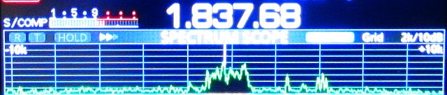
Image with active loop on a 50 cm pole.
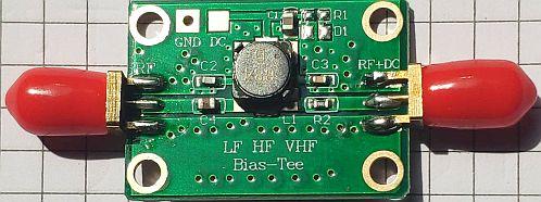
A choke balun (line insulator) was used for output coupling. That is easy to assemble for home brewers and ensures transmission of a very broad spectrum.
A DC power for the amplifier can be supplied through the choke balun, but to avoid pre-magnetization of the coil core, supplying was chosen via two large chokes.
An interesting experience was keeping the output floating, because this made the reception quieter. A PNS statement (probably nonsense statement) may be that the ground plane of the PCB, which was connected to the ground of the output connector, despite its small size, acts as a mini whip antenna sothat unwanted signals reach the receiver via the screen of the coax cable.
OTHER SIMPLER CIRCUIT
This performs almost as well as the previous system and for its simplicity it is my preference. If one compares both systems at some distance, the difference is minimal.
.jpg)
With the same PCB this circuit can be made.
In the following images nothing was changed to the receiver (IC7300). It was switched from the inverted V (2 × 16.55m) antenna to the active antenna as quickly as possible to get both images as identical as possible. An automatic antenna tuner per amateur band ensured that the inverted V antenna system was brought into resonance. Before taking the test, the amateur band or a bit outside of it was tuned to a signal that was as constant as possible. It will be clear that test were not done at the same time of day.
The dipole (inverted V) has a 12m mast as its suspension point. The loop was mounted on a 1.70m wooden pole.

Bacons 50.425MHz and 70.070MHz.
BBC Radio 4, 198 kHz.
Not disappointing for such a simple circuit, especially when you actually compare it with other designs published on the internet.
This result with such a simple circuit was a pleasant surprise. If you look closely at the images, you will see that the loop has a little less signal than the wire dipole. However, keep in mind that the top of this antenna is 12 m and the system is matched into resonance with an automatic antenna tuner. The loop, on the other hand, is on a 1.70 m pole and is broadband.
EXPERIMENTS WITH AMPLIFIERS
The advantage of a balance circuit is the suppression of even harmonics.
 To my surprise, someone had already experimented with the balanced design.
He wrote:
“Tonight I made the loop Amp as it is on your site, There were still a number of new RCA 2N5109's from the 1970s!
The amplifier works well, even below 100 kHz it is two S points stronger than my old BC design. Above 3 MHz to 15 MHz, the gain increases even more and should actually be reduced a bit because the S meter already shows 1.5 S unit. On the other hand, all stations are very strong. It sounds like a good S/N ratio, it works better than with the INA amplifier.
The reception from 50 to 500 kHz is simply superb and can compete with an expensive long-wire antenna. The loop (130cm) with the internal conductor as one turn is approximately 4 µH.
When I insert a second winding (double loop) it becomes close to 10 µH and the reception in this range is even better. The signal of BBC on 198 kHz is over S9 and you can hear all beep and whistle beacons below 100 kHz.
I'm probably going to use a relay to choose between one or two turns, because it is really worth it!”.
THE BEST TESTED SYSTEM
This design was chosen because it met our requirements: simple, well-performing, with standard components and suitable for DIY.
If a circuit has too much gain then it can be reduced with a resistance. This is the old larger PCB that was well suited for experimenting.
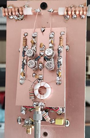
 Transformers at the input and output cause losses or limit the bandwidth and can have unwanted resonances. Due to (sometimes) many windings with extra capacitance, the question is what remains of such a balancing. That is why I prefer a toroid core as a line insulator/choke balun, where it is possible to separate windings
 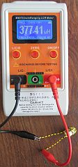 from each other so that they do not lie against each other along their entire length. Moreover, that system is suitable for DIY. The toroid core used here is type 2P80 and with 10 bifilar turns, the inductance is approximately 377 µH measured with a Chinese M4070 LCR meter.
It can be replaced by AMIDON FT50-W.
 If you order PCB's from PD0EEA, the white (2P80?) toroid core is included free of charge.
If there is too much gain, one can apply a resistor across the choke or use a suitable attenuator at will. The decoupling has become a choke balun or line insulator.
So one is not so dependent on the properties of a transformer or other system as coupling. Strangely enough, unwanted interference was much less. For the time being I assume that asymmetrical interfering signals have less chance of entering the receiver due to an improved balance.
There will be comments of: "The output is not 50 Ohm".
No, that is not 50 Om, but the transceivers or receivers used for testing were not affected. In addition, the impedance at the input of receivers is rarely exactly 50 ohms.
In the meantime, various well-intentioned comments or suggestions have been received along the lines of: "That is not good, why thst not, too much amplification, it could be better, it causes too much noise, the impedance is too low, the collectors are almost short-circuited, etc. " However, the circuit works in practice, is our experience after extensive experiments. The disappointing thing is that all consultants do not present a simple and working circuit that can compete with the design in this article in a comparative practice test. When a better (KISS) pre-amplifier is designed, we as experimental radio amateurs would like to know more about it!
The operation is the same as the previous circuit, except that it has been slightly modified due to the small print design.
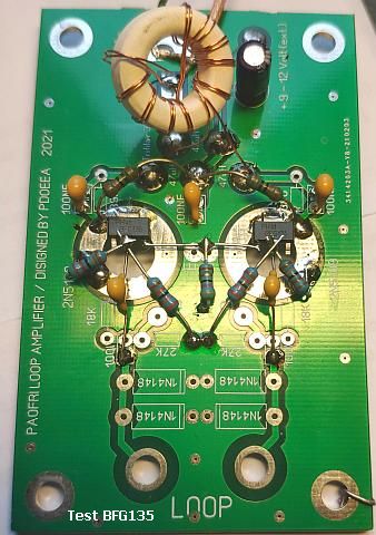
The reception range with 2N5109 or 2N3866 is at least 30 kHz to 146 MHz and with BFG135 to 220 MHz.
With the bottom of the loop at 50 cm above ground, the Bergen op Zoom repeater can be heard on 145.625.
The distance to the repeater is approximately 30 km.
The 70.070 MHz beacon at 40 km use a Big Wheel horizontally polarized antenna and the signal is received more strongly than with my vertical antenne on a 12 m high mast. Given the size of the loop, this band clearly shows horizontal polarization.
The result also depends on the beam angle of the opposing station. For example, if two stations close to each other at 40 m have the same strength with a 2 × 16.50 m dipole, then one of the two is stronger with the loop antenna than with the dipole.
ASYMMETRIC OUTPUT
|
 |
A considerable simplification can be achieved by applying a single ended output. No transformers or baluns are needed, which can be frequency dependent.
Various attempts were made to obtain an even simpler design.
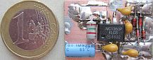
PD0EEA came up with the bright idea to design according to the internal circuitry of many ICs, such as an MC1350. This was and is still used in DIY projects and it is installed in many transceivers.
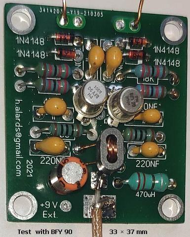
It is not clear to everyone how the circuit works. In one transitor, the collector is decoupled by a capacitor and then acts as an emitter follower. The signal is passed through the emitter to the other transistor. The latter serves as a grounded base amplifier, but also as a grounded emitter amplifier. The result is that with this transistor a signal is produced at the collector which is the sum of both signals because they have the same phase.
 |
|
|
In the original schematic, you only have to install one capacitor at a collector to ground and insert a common emitter choke. It remains to be tested whether the result is the same as that of the original design. If that works out positively, it will come even closer to our objective: to present a system that works as simple as possible (KISS) and performs with little effort.
The advantage of this circuit is a symmetrical input and an asymmetrical (coaxial) output without baluns, choke baluns, line insulators or transformers.
The Korean 2N5109's performed just as well as the original "vintage" RCA 2N5109.
Another idea that was tested is a grounded base circuit, but the gain is less than with a grounded emitter circuit, which was to be expected.
That was improved by combining both systems, but with two extra transistors!
It is also being investigated whether further simplification is possible.
This is the result of the left schematic.
LOOP CONSTRUCTION
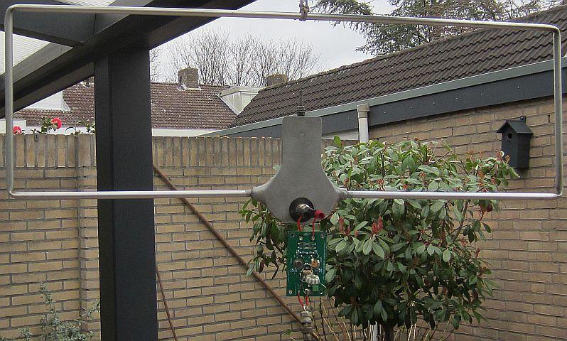
As an experimet I used a pair of home brewed 2 m antennas as a loop. They works, only the strength of the signals is less and it is still better to use a larger circumference.
We are still working on a sturdy and simple construction of the loop antenna. It could also be a 4 × 100 cm square. That's close to the circumference of 120 cm a circular loop. It can be made from Alu strip or Alu corner profile for strength. An angle up so that it becomes unattractive for birds to sit on.
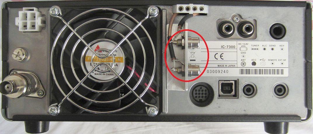
IC7300 WITH ACTIVE ANTENNA
 |
 |
 |
 |
 |
Feedback from VK:
The performance is excellent and they outperform my early model Wellbrook with much less IMD especially on the broadcast band. HF performance is superb.
I built a small 30 cm unshielded loop and mounted it onto my car, which I use for QRM tracking.
I was so shocked when I was driving around in the city listening to Ja's, YB's, HL and USA stations with excellent signal noise ratios. It works very well on 40 meters in this situation.
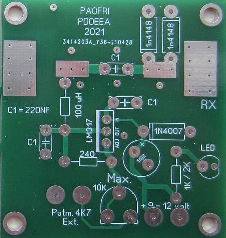
Universal supply.
![]()