ACTIVE LOOP ANTENNA FOR RECEPTION
![]() 25-jul-2023
25-jul-2023
This active loop design is used for WebSDR: http://mwiek.nl:8073/
%2010-dec-2022.gif) |
 |
.jpg) |
.jpg) |
 |
Note: Due to a lot of experiments and tests, many hams do not know which schematic to follow. The aim was to achieve the best result with as few components as possible.
Also note that during the development process the value of the components has changed.
In the Netherlands, amateur radio operators with antennas that are too short will benefit from the left-wing schematic because the 80 and 160 m bands clearly stand out.
The more even characteristic of the right-hand design is probably more attractive to others.
Unfortunately, the measurement method used here does not say everything about performance.
The graphs are a rough indication of what you can expect, because upon receipt it appears in practice that there is not much difference between the various designs.
If you search the internet for active antennas, you will find more than 80 designs. Partly commercial, but the majority are own designs of radioamateurs or electronics hobbyists.
Why an active antenna again? This is due to a common phenomenon among amateur radio operators: you keep experimenting, investigating whether something works, can even be improved and whether it also works well with fewer components.
The design was actually intended for the HF bands, but it turned out to work well from 100 kHz to 70 MHz. Even 2 m can be received.
This active loop antenna is the result of at least two years of experimentation. First by PA3GZK; he has made and tested many of the active antennas published on the internet. Finally, the antenna was equipped with a broadband amplifier IC. Because I was curious whether the system would also work well with discrete components, my experiment was started. Also because not every possible homebrewer is handy with mounting almost invisible ICs. You experienced it yourself, hold your breath and when it falls to the ground, it is almost impossible to find.
Because I have been a 24/7 informal caregiver for over 24 years, I can not test everything intensively. Fortunately, PA3GZK and PD0EEA have helped to test or suggest changes to the designs over and over again.
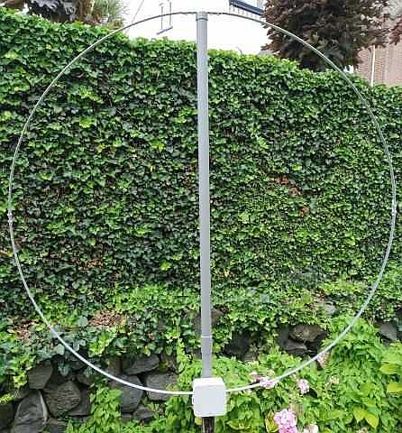
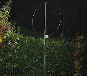
DIAMETER ANTENNA
It turned out that a loop worked best. A mini whip performs well on top of a building, on a dike or in an open field, but in a residential area it picks up too much interference. This is less with a loop and can reduce a spurious frequency by rotating it. PA3GZK found that a diameter of 1.20 m was optimal. That was a compromise between sensitive reception and sensitivity to direction. With a larger circumference, the reception becomes stronger, but a signal can be turned away less well. This is better with a smaller loop, but the reception becomes weaker.
After a lot of experimentation, the next design performs with as few components as possible.
It can be seen that a smaller diameter is mainly at the expense of the lower part of the HF bands.
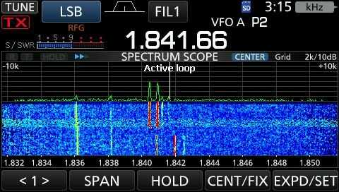
The loop with amplifier had a dip between 2.5 - 3.5 MHz. With a 1µF coupling capacitor to base, the level is lifted a bit. By applying a voltage across the limiting diodes, it is possible to attenuate the received signal. It turns out that the two 220 ohm resistors across the loop improve reception and make gain more even. Perhaps this is also because the two resistors force a better symmetry. The improvement is striking.
 |
 |
The previously shown version (2) 15-Feb-2022 performs satisfactory, but in past year extensive experiments were again carried out and it appears that the best result was achieved with version 31-Jan-2023. Note that the values of resistors and capacitors have changed. The collector current per transistor is set to 25 mA so that the system suffers less from overload.
POWER SUPPLY
.jpg)
.jpg)
The supply voltage is not critical, see above but with about 14 Volt it is optimal, so that a "standard" 13.8 V can be used.
I use a constant current source for the power supply. This is to limit the current during experiments in the event of a possible short circuit.
Some have doubts about using an LM317 because this semiconductor is said to suffer from noise. If so, this noise is negligible compared to the ether noise.
If you have a properly calibrated S-meter, it will already indicate S3 or S4 due to the ether noise.
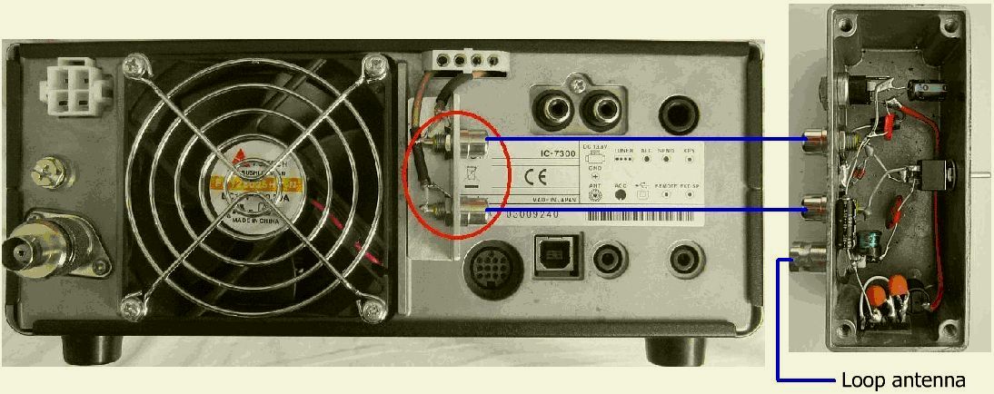
Here the well-known IC7300 modification has been carried out so that the active loop antenna can be connected.
TRANSISTOR
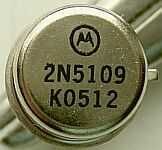
Why specifically use a 2N5109? Well, there were still original Motorola's left over from constructions and experiments in the last century. These semiconductors appear to be robust. Because of the many tests with this active antenna, more were needed. It seems that the Chinese have acquired rights to reproduce the 2N5109 and with some trepidation a dozen were ordered from China. They (production K0512) are not inferior to the original Motorola's. The spread in Hfe is about the same as the originals. Ten more were ordered at a later stage, but they turned out to be number K0342. In the table you can see the spread of both.
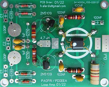
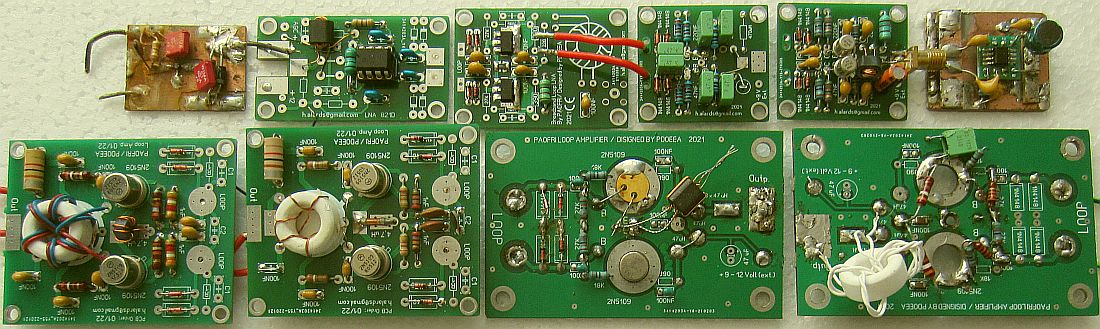
PRINT DESIGN
The antenna was intended as a DIY project, but it appears that some are unable or do not have the time to make it. Due to multiple requests, PD0EEA designed a PCB and shipped them domestically and abroad. See the bottom of this article for contact with PD0EEA. Ready-made antennas have also been ordered.
Unfortunately, there are people who think that he earns well with his activities, not so, it takes a lot of time and work and it is done to help the fellow amateur on his way.
The print design has been made as universal as possible, so that there is room for experimentation. For example, one can opt for a symmetrical output or mount a capacitor parallel to the loop. It is also possible to install a capacitor and/or resistor in parallel across the base.
One may wonder whether a better match to the receiver is necessary, after all the input impedance of an average amateur transceiver is rarely exactly 50 Ohm. The coaxial cable between antenna and receiver then acts as an impedance transformer, so that the loop amplifier is terminated with a load other than 50 ohms.
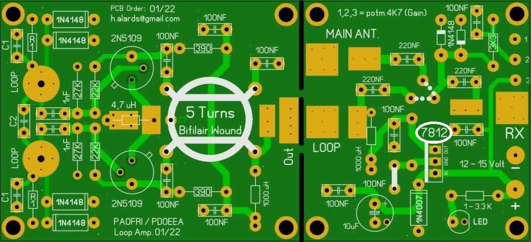
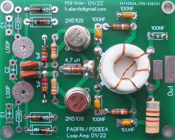
The print design has been made as universal as possible so that there is room for experimentation. When ordering the white ring core is included.
The original PCB design was designed for an LM317. With the connections shown above, it is now suitable for a 7812.
Please note that this IC must be mounted reversed!
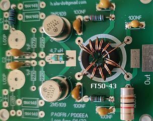
Instead of the supplied white toroidal core, you can also use an FT50-43 with 10 bifilar windings.
The size of the loop amplifier board is 65 × 52 mm and the power board is 52 × 49 mm.
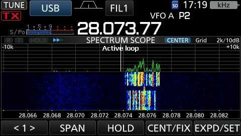
IN OPERATION
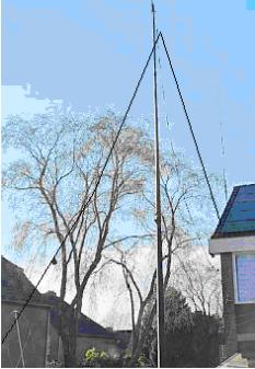
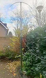
Despite its relative simplicity, the antenna works quite well from at least 100 kHz to 146 MHz. It can be the solution for people who like to listen to radio stations, but do not have the opportunity to set up a high or long antenna.
As a performance reference, a 2 × 16.55 m inverted dipole with the top at 12 m was used. For each amateur band, an automatic antenna tuner match the system into resonance. The receiver was an ICOM 7300. My tests were done with the loop 50 cm or 170 cm above the ground and that was not disappointing. It is therefore expected that the result will be more than satisfactory with a higher set-up. I am thinking of listeners who live in a flat and only have a small balcony at their disposal. If the antenna is mounted rotatably, a noise signal can be considerably reduced and a weak station set to maximum. Performance depends on conditions, time of day and beam angle of the transmitting station. The signal from the loop antenna can be less strong than the dipole, but also stronger.
It once occurs that two stations on 40 m happened to be on exactly the same frequency. I didn't notice that, but when switching from dipole to loop and back, only one of the two could be heard. So one transmitter on the dipole and the other transmitter on the loop.
Comparing antennas with each other must be done over a longer period of time in order to be able to assess them properly.
With regular use, I find it a godsend to listen to stations without having to tune the transmitting antenna when searching on the amateur bands.
SHIELDED LOOP
Does a shielded antenna make sense? The three testers are not sure about that. Sometimes it seems that a shielded loop receives less interference, while at other times it doesn't matter. If one analyzes the antenna, it turns out to be a so-called Halo antenna that is fed with a coupling loop.
Based on this finding, one could deduce that a shielded antenna has no advantage. However, it seems that a jamming signal can better be turned away, but more research is needed to confirm it.
A disadvantage may be the capacitance of the shield with the inner conductor, it increased the input capacitance of the amplifier.
A circular antenna is not absolutely required. A cross-shaped support with a wire as antenna is also suitable.
A loop of the same size with a diameter of 120 cm was used as transmitting antenna for the spectrum analyzer.
As the frequency increases, the decreasing gain closely matches that of the receiver section in common HF transceivers.
One may thought that we milk the design gradually, but it appears to me that a choke balun between antenna and amplifier greatly reduces a certain type of interference. A station with the loop was easier to copy than with the wire antenna. A possible explanation is that an unwanted signal from the antenna still reaches the receiver via the copper surface of the PCB.
PD0EEA found that a capacitor parallel to the loop improved reception at 80m and below. I have also established the latter.
As a result, we are still testing this last idea.
A preliminary conclusion is that the parallel capacitor should have a value of 100 - 150 pF. I used 120 pF. Incidentally, PD0EEA has already taken into account the possibility of an extra capacitance in the design of the print.
With the 1 µF coupling capacitors to the base, the reception of BBC 198 kHz and 80m improves, while it decreases on 50 and 70 MHz.
TWO RECEIVER INPUT.S
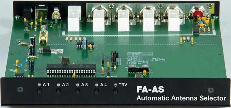
If your radio does not have two antenna inputs, there are various options on the internet to perform. Another option is, for example, an antenna switch from Funkamateur as a kit.
https://www.box73.de/product_info.php?products_id=3686
![]()
![]()
![]()
DEVELOPMENTS AND EXPERIMENTS
PD0EEA has experimented again and is currently using this design.
A selection of my experiments.
.gif)
.jpg)
.jpg)
Used PCB installed with other or additional components for testing the design.
Measurements at the Feb-2022 design showed that there was not half the supply voltage across the collector. To achieve this, other basis resistors had to be mounted. This was tested on a virgin PCB and because I had enough 470 nF capacitors, they were mounted in all places. The impression is that this modified design works even good as the Feb-2022 design. It is currently in use by me.

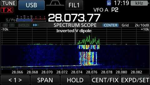
The signal from the active loop antenna (Version 03-dec-2022) is usually slightly less than that from the inverted V wire antenna, but often weaker stations can be received better.
Especially very weak CW signals on, for example, the 20m band. Virtually impossible to take with the wire antenna, clear to receive with the loop.
.gif) |
 |
.gif) |
 |
.gif) |
 |
The best method to measure the system turned out to be a Gamma match at the zero point of the antenna. All other methods are affected by distance, direction of rotation and shape of an antenna providing the control signal.
The amplifier can be tested via two series resistors of 100 Ohm.
The decreasing gains in the images are actually less strong because with increasing frequency the electrical size of the loop increases and will therefore receive more signal.
Incidentally, the supply voltage is not critical and at a lower voltage all three work the same.
.jpg)
.jpg)
Version 10-Dec-2022 first tested with the correct components on previously used PCB, then replaced by a new PCB with only new components.
When experimenting I usually use unsoldered components. If a design works satisfactorily, it is neatly installed with new copies. In schematic (version 10-dec-2022), everything have been selected for as much equality as possible. Simply because the measuring equipment is there. So also the two 2N5109's.
The completed PCB was tested, and it turned out that one 5109 was defective? Took it out and measured the gain again, was "good", put it back in, didn't work! The circuit worked with another tested 2N5109. Apparently it didn't perform with the "defective" transistor when voltage was applied. It is therefore wise to take this experience into account.
.gif)
.gif)
Here you can see a typical phenomenon when I experiment: a test circuit with used components and PCB works better than the end result with newly selected components.
Two copies of the right PCB were made and both were identical in result.
It turns out that an matching system between loop and amplifier produces more signal on the higher HF bands.
The matching is made with the white toroid core. There are 20 turns installed and the taps are at 5 and 15 turns respectively.
The disadvantage of such impedance systems is always at the expense of a frequency range, which is apparent from the images shown.
With a 2k2 potentiometer on the right and removal of two 220 Ohm resistors, a better balancing and also a bit more gain is obtained. Adjust for equal collector voltage.
%2031-jan-2023.gif)
.
The left system is, in my experience, the best compromise for receiving from 198 kHz to 70 MHz.
To obtain a wider spectrum, two identical amplifiers were connected in parallel. One with an autotransformer and the other without. But that was at the expense of the upper part of the HF bands.
|
|
|
%2027-dec-2022.gif) |
 |
If a diode is used for the base set-up, the circuit becomes even simpler, but the collector resistance must then be 820 Ohm. As a result, the negative feedback increases and the input impedance decreases and the gain drops. With a 4 : 1 transformer at the input, the match is better and a flatter wave pattern is obtained. The overall gain is much less than the 10-Dec-2022 circuit.
As an experiment, a preamplifier with two J319 FETs was added. With the gate resistance you can adjust the graph.
Unfortunately, it is not yet possible to get the 80 and 160 m equal to the higher frequencies.
The experiments show that a matching network at the input mainly favors the higher part of the HF bands at the expense of everything below the 40m band. The best system is then an HF autotransformer with a turns ratio of < 4 : 1.
Zie also experiments with active antennas:
ps://pa0fri.home.xs4all.nl/Ant/Active antenna/Active receiving loop antenna.htm
https://pa0fri.home.xs4all.nl/Ant/PA0FRI's actieve antenne/PA0FRI's actieve loop antenne.htm
| ORDER PCB |
| The boards can be ordered via h.alards@gmail.com For more information, use hollandshortwave@gmail.com |
Sie können Ihre Bestellung oder Korrespondenz in deutscher Sprache aufgeben.
![]()