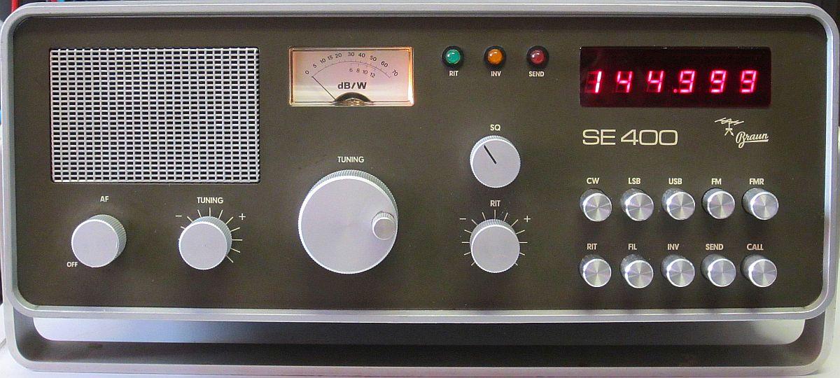
BRAUN SE400 MODIFICATIONS
INTRODUCTION
A few years ago I acquired a Braun SE400 2 m transceiver from an estate. Devices of the deceased had been selected and the rest would be disposed of. Before doing the latter, I was asked if there was anything else for me. Obviously, the Braun caught the eye and was saved from destruction. At the time (1975) an SE400 was a flagship among all other 2m sets and cost about DM 2500, while a middle class car was DM 5000. Probably there weren't many radio amateurs who could or were willing to spend that amount for a handmade transceiver!
The acquisition was taken home with a happy feeling and there the outside cleaned, the inside inspected and then tested. It all looked neat, a resistor had been removed, a resistor mounted in a other place and the output was about 6 W, less than 10 W according to the manual. At the time, a common complaint was that the 10 W output power was not reached and someone recently reported that his Braun only delivered 8 W.
Due to ongoing projects or experiments at the time, the set ended up temporarily among other stored items.
TRANSMITTER
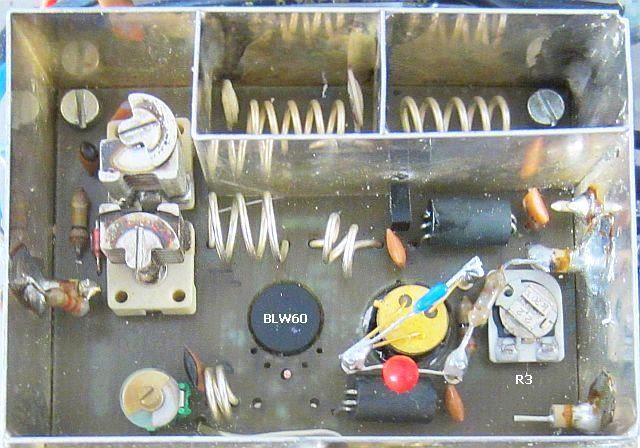
![]()
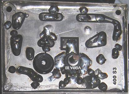
OUTPUT STAGE WITH BLW60
 |
|
Meanwhile the project started again and I tested a few things. Power output was not stable. It looked like oscillating, but it turned out to be the sliding contact of potentiometer R3. Therefore it was removed for safety and mounted a more professional type.
It's a confusing matter with SE400, SE401 and SDE402 schematics. My Braun is a SE400, fitted with a BLY88A in the output stage, while it would be in a SE401. It is not known whether it is original or whether it was installed by a previous owner.
Given the low 6 W power, you never know what was done with it, the BLY88A was removed. Also because with full drive the base became negative.
Decades ago I experimented a lot with geveaways from Philips: BLY87, BLY88 and BLY 89. Sometimes I did something wrong due to inexperience with the then modern VHF transistors. Among other things, it happened that the output suddenly decreased. The "transistor" consisted of many transistors connected in parallel and some were defective.
Surprisingly, when searching my stock of components, a few new BLW60 were found. I didn't even know they were there anymore.
This transistor is rated for 45 W ouput, but needs more drivel. If we aim for approximately 10 W, the BLW60 must be able to withstand an unloaded set or a high SWR.
 During the first tests with a BLW60, a tantalum of 1 µF caught fire with a blowtorch. It was the capacitor that decoupled the drain circuit. Faulty tantalums will be a familiar phenomenon among experienced DIYers. The burnt one was replaced by a 470 nF capacitor.
Incidentally, the resistor, which is connected in parallel to R3, is listed in all schematics as 820 Ohm, but 1.8 kOhm has been mounted by the manufacturer!
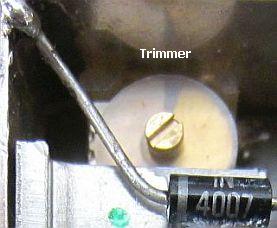
To get any output, C5 and 2 × 22 pF at the base were removed and the 10 pF coupling capacitor from the driver to the output stage was replaced by a 22 pF trimmer for a more accurate adjustment.
Furthermore, it turned out that the base no longer became negative after full drive at about 6 W ouput. Was really something wrong with the BLY88A?
At a later adjustment for more output, C10 (13pF) was set to maximum, so a 4.7 pF capacitor was mounted on the track side in parallel with C10.
DRIVER STAGE BFS22A
The positive voltage at the base of T8 was also negative at full drive. This is a result of too little base current of the bias setting. A design flaw in my humble opinion. An improved basic supply can be achieved with a few extra components.
Because it turned out that potentiometer R3 of the output stage was unreliable, as a precaution, R2 (at least 45 years old) was also removed from the driver stage by cutting the three legs. The latter were used as a soldering point for the components to be mounted.
I prefer to use fixed resistors for the base voltage with HF amplifiers. First the value is determined with a potentiometer and then replaced by a resistor.
If desired, the potentiometer can be kept and set to maximum resistance.
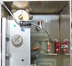
This setting improved the control power and for even more drive the 10 Ohm resistor from point C to MP2 was replaced by an 1 Ohm resistor. In the schematic and the image you can see how I installed two resistors and one diode and further a trimmer on the place of a 10 pF capacitor. The 1N4007 is mounted with thermal paste onto the L-profile heatsink to monitor the heating of T8. Actually, that is not necessary because the heat sink keeps the BFS22A at a more or less stable temperature.
OUPUT 12 W
After adjusting all the pre-stages at 145 MHz, the maximum output was 12 W. Probably more power is possible, but the question is whether the power supply can handle that with long transmissions.
POWER SUPPLY PCB
Contrary to the diagram, two resistors have been mounted on the PCB of the power supply to increase the 4.95 V stabilized voltage of IC2 (µA7805) to 5.28 V. The print traces were factory made for that change. Why that was done by the manufacturer remains a question because it was not present with the SE400's of some other owners.
IF FILTER
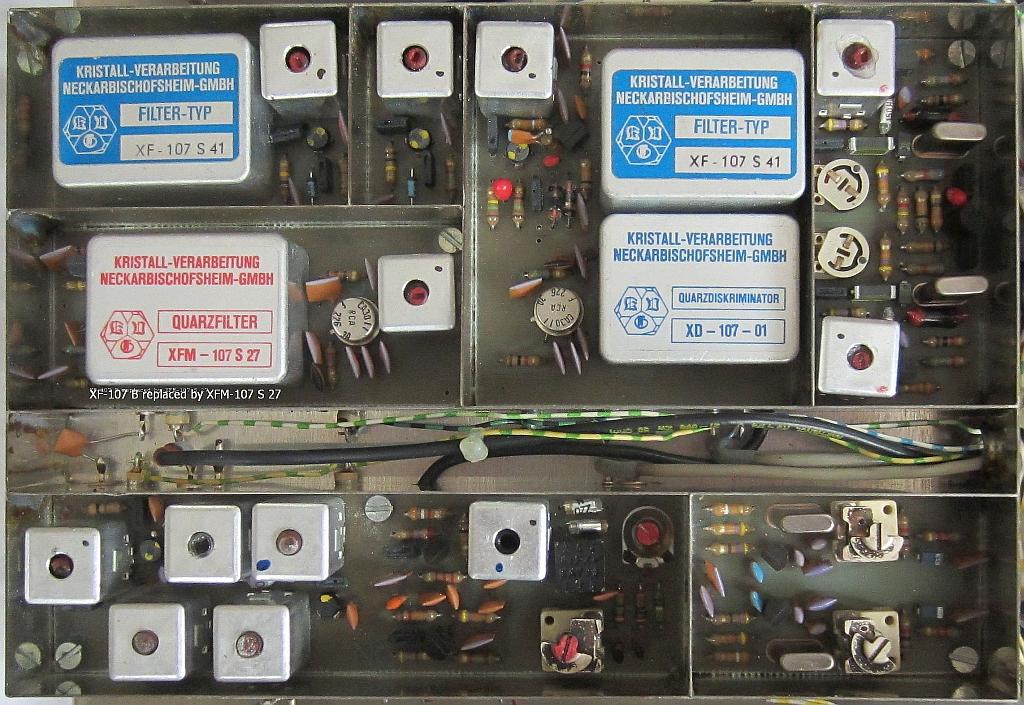
A KVG 10.7 MHz filter XFM-107 S 27 was purchased via eBay. This filter is approximately 15 kHz wide, but is constructed more symmetrically than the original XF-9B filter. That is why it fits better in the 12.5 kHz channel grid and that is noticeable in practice. Without other changes, the old fiter has been removed and the new installed.
![]()