TEN TEC OMNI VI MODIFICATIONS
This article is in progress!
INTRODUCTION
There are several modifications for a Ten Tec OMNI VI, but mine I have not come across as such on the Internet.
RX ATTENUATOR ON 160m
Monteer 100 nF parellel aan de gemarkeerde condensators (C3, C10, C23, C38, C39, C40, C41 en C49).
If I inject my Corsair II and Omni VI with a 50 µV signal the S-meter indicates 2 - 3 S-units less than S9 on 160 meters. I have searched for a long time to find the causes and apparently discovered one of them. Furthermore, I suspect that the inductance of the balance transformer (T3) windings is insufficient for this band.
|
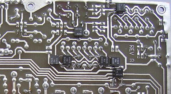
BPF/FRONT END BOARD (81593), 8 × 100 nF en 2 × 470R |
The total coupling capacitance for the 160 m signal is to small, especially compared to a 50 ohms signal of the source. From the antenna input to the 4 × J30 amplifier are respective in series C3, C10, C23, and then in series with C38, C39, C40, C41 in parallel.
That's a total of only (3.3 × 40) : (3.3 + 40) = 3 nF! Also, C42 (10 nF) and C49 (10 nF) are insufficient. The S-meter indicate a more correct value if a 100 nF capacitor was installed onto the track side in parallel with each of these capacitance's. A significant improvement but it does take some track's investigation to locate the right components. The picture may facilitate the precise work.
Two 470R resistors in parallel with the original 470R resistors is a modification extracted from the internet. You can remove the original ones and mount 220R resistors instead.
S-METER ADJUSTMENT
It was not possible to adjust the S-meter in my 5th.hands FT-736R according to the manual: 0.8 µV = S3 and 50 µV= S9. With 0.8 µV the pointer stays in the left corner and with 50 µV the pointer moved just over S9.
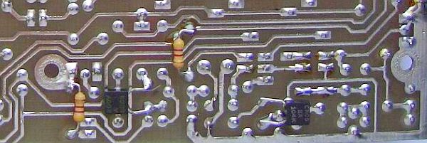
Overall improvement was possible with (fig») a Schottky diode (BAT85) parallel to D4 (1N4148) at the track side. S3 = 0.8 µV still fails, but S7, S8, S9 and S9 + are closer to the truth. If you perform this change, do not forget to readjust L3 and L5!
AGC
|
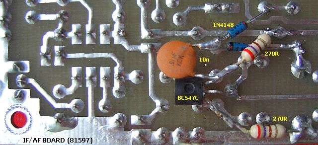
Bruggelijkrichting voor het AGC systeem. |
|
The receiver has regularly a tic-tic jam like an electrical fence system, but that is not the source. Atlas210x/215x, Corsair II and other transceivers with a LF-derived AGC system have the same inconvenience. In Atlas types it was almost eliminated with a
bridge rectifier for the AGC system.I did it again in an OMNI VI and the interference is much reduced. The design includes an additional transistor (BC547) as phase shifter with a gain of 1. The emitter is not decoupled. The circuit is parallel to the base of Q3 and BC547's collector signal is rectified with two extra diodes (1N4148). D6 and D7 (1N4148) plus the extra diodes are a bridge rectifier. Purists will state that the 220R resistors should equal to R6, but with the values shown it works satisfactory. Again, L3 and L5 have to be adjusted again!
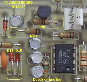
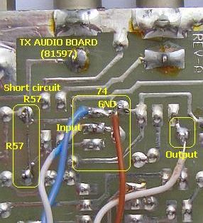
NEW SPEECH PROCESSOR
A RF speech processor (IF Clipper) with an 455 ceramic filter:
A limiting RF speech processor. The reason is that the original LF compressor/clipper is not really effective. Incidentally, those of the Corsair II is just as ineffective and therefore it was never turned on by me.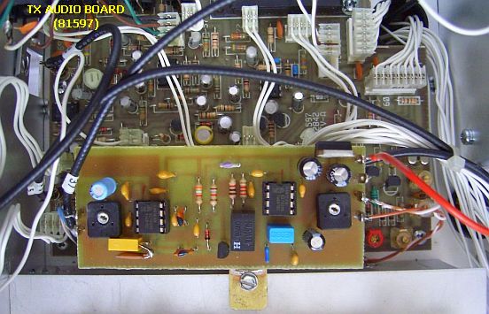
![]()