RESTAURATION AND MODIFICATION OF YAESU FT-757GX AND FC-757AT
![]() 30-nov-2014 In FC-757AT battery CR-2025 replaced by type CR-123
30-nov-2014 In FC-757AT battery CR-2025 replaced by type CR-123
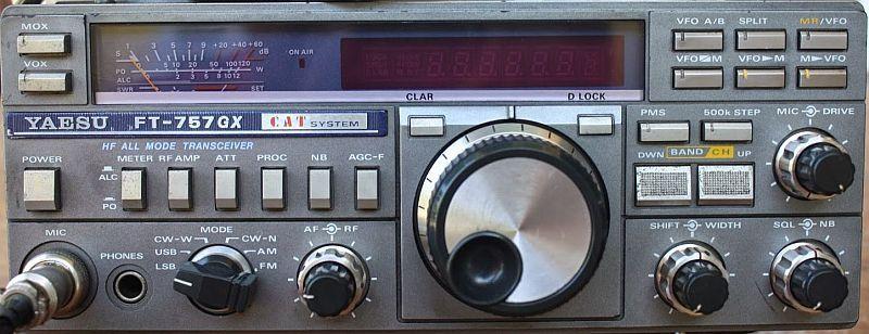
YAESU FT-757GX ("Mark 1")
FT-757GX
INTRODUCTION
In this article only those items are shown which inspired me during restoring, adjusting and working with the set.
On the Internet there is enough information about this FT-757GX; an older version of YAESU, also called Mark 1, with a six-position MODE switch. The newer model has the MIC / DRIVE controller at this position and has electronic mode switches on the right side.
In addition to LSB, USB and CW, AM and FM mode also work well, there is an electronic keyer, CW filter, 10 memories, two VFOs, shift mode and adjustable RF gain. Often, one does not know about the correct use of RF gain. When listening to a station, the amplification is reversed so that it is still understandable and if it sounds too soft, it adjusts with volume control. This reduces the strength of all unwanted signals below or above the desired station. It can still be optimized by "playing" with SHIFT and WIDTH.
At the back are many other settings or connection options. In addition, there are controls that are often lacking in more expensive radios such as the above-mentioned RF gain, SHIFT, WIDTH, and NB. Combined with a coupled AGC, a weak or distorted station can be understood by the proper operation of these organs. Thus, with all of the possibilities mentioned, the reception quality can mostly "tuned" to the counter station to obtain a quiet reception, which is usually impossible or difficult to achieve with many other sets. With many types of interference above a certain interference level, the adjustable noise blanker works well without affecting the modulation of the receiving station.
If the lid and also the cooling block become too hot, the built-in fan goes on when transmitting. With a drop of oil as a renewed lubrication it turns out to be undesirable.
In short, an old model transceiver that is still good with time and does not undergo much more modern sets.
It seems that this transceiver has a bad name and I wonder why? A widely-heard complaint is that the receiver is too noisy. Indeed, this is true if the preamplifier is on, it is only necessary if you are mobile and with a short vertical antenna. Do not use a preamplifier with a "normal" outdoor antenna (for example a dipole). As a test, disconnect the antenna and turn the volume control to the maximum. Too much noise? No because you will hear nearly nothing. Turn the volume control back to its usual position, reconnect the antenna and listen to the 10m band. The noise increases. The receiver's own noise is thus lower than the band noise and then the receiver without a preamplifier is sensitive enough!
Furthermore, there were about 200 Hz drift of the VFO after the set is switched on. This restored transceiver remains stable and does not drift to me.
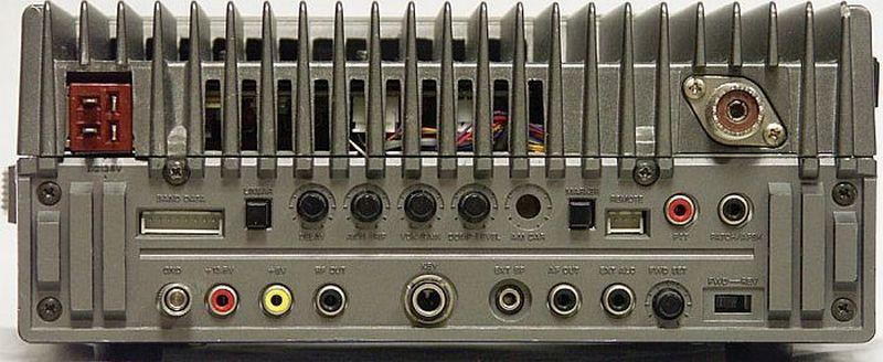
Many possibilities at the backside.
DOUBLE SIDEBAND CLIPPER/PROCESSOR
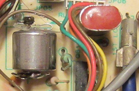
I did not like the («fig) original LF speech processor because it produces an unacceptable distortion. It is no more than a simple system: one transistor as amplifier and a collector circuit with two germanium diodes anti-parallel as limiter.
The later FT-757GXII has a built in RF speech processor.
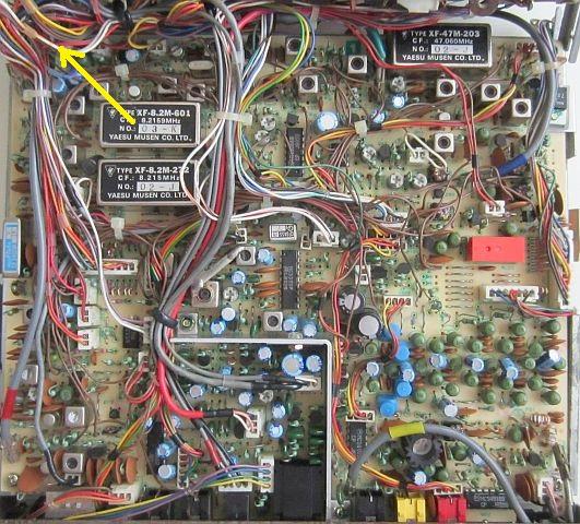
A RF clipper works better with less distortion. I had installed a DSB (double side band) clipper in a Kenwood TS-50 and was looking if this system could be applied without much "demolition work". The most suited point was the transmit portion of the RF UNIT e.g. buffer amplifier Q40 (2SK120) directly in front of the crystal filter.
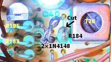
The («fig) drain of Q40 is loaded with IF transformer T20 and resistor R184 (10k). With sufficient drive and 2 × 1N4148 diodes anti-parallel across T20, the system works as IF limiter. The subsequent crystal filter ensures suppressing of undesirable harmonics. It turns out that drain's output was sufficient for a reasonably effective clip level, but even better when damping resistor R184 was removed. Here, it was done by cutting the ’top’ leg of R184. Damping still occurs when the diodes begin to limit.
The result of this simple system is not spectacular, but works better than the original processor. Moreover, almost no one notice that a clipper is active, it can remain permanently. The PROC button could be used for something else. Installation on the track side, but if you have a steady hand, it can quickly on the component side. My method was solder between the lower end of resistor R185, and at the top of the cut leg of resistor R184. I expect photos and drawings are clear enough for easy assembly.

 The compaction of the signal is clearly seen on («fig) a scope, which means that average output power is increased. Clip level can be adjusted with (fig») MIC volume knob. Overdriving the output stages is almost impossible, but with too much microphone gain your modulation will sound rough. Besides T20 it is better to readjust all TX IF transformers T20, T21, T23, T24 and T25 as described in the manual. It's a piece of cake and there is no need for special measuring equipment
.
For increased microphone gain find the slide switch in the left front corner on the LOCAL Unit PCB behind the microphone connector. Slide the switch into the position as shown in the photo.
RESTAURATION
 |
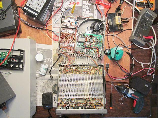 |
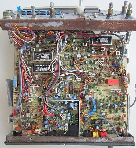
In the past, I took over two partially defective PA’s of someone, mainly to have the power transistors as a backup for something else. The stuff has been unused for years in my junk box. Recently I received two stripped FT-757GX transceivers from a dealer with the question: "Do you have anything to do with it or else it will disappear in the trash can." Both sets were flooded aboard a ship with seawater and thereby heavily damaged, then disassembled and stripped of various buttons and components. In addition, many wires were cut through. Boards with their components looked a bit messy, but were found to be in good condition after cleaning. Normally, I do not do anything with devices in such a state and will only store them for spare parts.
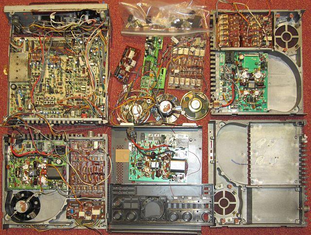
Because I have not had an FT-757GX yet, curiousness was an attempt to make something of the scrap. After a lot of "test and measuring" I finally succeeded in assembling a well-functioning transceiver. The remains (fig») are saved as "spare parts" because you never know!
BATTERY CR1/3N-P
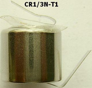
Left: new battery Sanyo-FDK CR1/3-T1. Right: the old battery pack on the LOCAL Unit at the top of the PCB.
In many cases, the CR-1 / 3N-P memory battery has to be replaced. This is noticeable when the display on the 40m band starts with 7000.0 MHz after turning on the set. The 3 Volt cell is soldered on the LOCAL UNIT with two lips, but to get to the track side, the entire print must be dismounted.
That's a whole operation, luckily there are alternatives! With a flat screwdriver, by wiping between point-wise lip and battery, the two lips got loose and the battery can be removed. Then (Fig.) Replacement type Sanyo-FDK CR1 / 3N-T1 could be soldered to the upright lips.
As usual, the local "Handyman" did not have the type of battery I needed in its stock. It could be ordered. You know how that goes; Wait a week, then drive to the mall by car, go to a payment garage and walk to the shop. On the Internet it turned out to be faster. Pay with Paypal, no postage and well packed in the bus the next day. I do not have a special connection with the supplier, but if you want to know: batterijenhuis.nl.
INCANDESCENT LAMP AS FUSE.
If the receiver suddenly does not work properly, make sure that the light bulb in the RF UNIT, which is used as a fuse between antenna input and receiver, is not blown. In one of the demolition sets I saw that a previous owner had replaced the lamp. It met, so I left it.
By the way, every 8V / 100mA lamp can replace the original type.
In the last century (!) I had a seafaring ham radio operator working with another YAESU rig, where I assisted him with his defective receiver. It turned out that that type of radio was also protected by a lamp. It was shown in the circuit diagram that I had in my archive by chance. With to a temporary bridge connection instead of the lamp, he could still take part in the amateur traffic with the set.
FREQUENCY RANGE
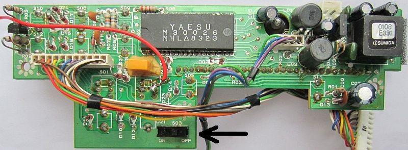
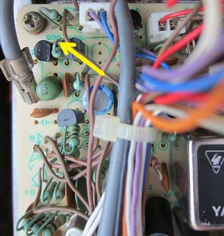
Increase frequency range with slider S03. PNP transistor Q03 (2SA733AQ) was replaced by a BC557 on the DISPLAY unit.
The frequency range can be extended to 1.5 MHz - 30MHz by setting the switch S03 on the DISPLAY UNIT to "OFF". The pictured image tells you more than a detailed description of the location of the slide switch.
One pin of PNP transistor Q03 (2SA733AQ) at the top left was broken at the case, so repair was virtually impossible. Using a BC557 proved to be a good replacement. Attention: The pinout is different from the original transistor!
OUPUT POWER CONTROL IN SSB
RF Unit, PCB at the bottom.
With the DRIVE button, output power can not only be set for AM and FM, but also for SSB. To achieve this, the RF UNIT resistor R179 (10k) must be cut between Q38 and Q39. It is true that for each band and mode the setting for a particular transmit power is NOT equal. Note that if you are using different transmission powers!
The final stage can deliver more than 100 W, and especially in the CB world, one tends to squeeze out more power. That's the reason why such an amplifier can blow up during an endless FM QSO or with an unusual high SWR of the antenna system. For a long life, it is recommended to fix the output to 100W. During the restoration it has occurred several times that the 100W set was unintentionally set to transmit without any load and, thanks to SWR protection, the final stage has always survived!
ALIGNMENT PROCEDURE
In older sets it is important that all plug connections and coaxial connectors have been disconnected, cleaned and reconnected. As an extra measure, I first brush a touch of special contact oil or contact grease with a brush. My experience is that future contact problems are largely avoided.
The "ALIGNMENT" procedure can be found by downloading the TECHNICAL SUPPLEMENT or SERVICE MANUAL from the Internet.
If power of your set is low, adjustments can often be limited to:
| 45 MHz TRIPLER |
| 15 MHz Regference Frequency |
| 2nd Local Oscillator Frequency |
| Carrier Point |
| Mode Adjust |
| BFO Frequency |
| Carrier Balance |
The Internet is talking about bad trimmers and advised to replace them with better quality types, but at this restoration all trimmers worked properly.
In subject (or step) H. Carrier Point of LOCAL Unit states that the frequency counter must be connected to J2008. The measurement can be made easier by using test point TP2001.
For CW mode, trimmer TC2004 must be tuned to 8215,900 kHz; this is an error in the manual! It must be 8216,600 kHz! Also the order of steps H and I must be changed in contrast to the manual.
So first step I. BFO Frequency and then step H. Carrier Point must be performed!
Additionally, when adjusting LSB, CW and SSB, leave the SHIFT button on the front plate always in the center position (12 hours). If you cannot tune the aged crystals to their nominal frequency, turn the SHIFT knob in LSB mode to get the right frequency, leave the knob there and trim the corresponding trimmers for USB and CW mode. The same can also help if you start the procedure with USB mode instead of LSB.
With step IF Shift Zero Point Set and VR2007, the SHIFT button can afterwards be corrected again to 12 hours position. If that does not help to get the oscillators at the correct frequencies, then USB and CW adjust slightly with VR2007 and repeat steps I and H.
It is then possible that the noise at SSB and USB no longer sounds the same in the middle position of the SHIFT button. By turning the knob, you will find the balance point. In this position, the button must be removed and replaced again, but now with the dash in the 12-hour position.
If this was not successful yet, the crystal oscillators you will have to add additional capacities or replace the crystals.
After everything is set as described in "ALIGNMENT", it may appear that the display indicates a few hundred Hertz too much or too little. That can be corrected by carefully turning the trimmer TC2006.
LIP REPAIR/MAKING
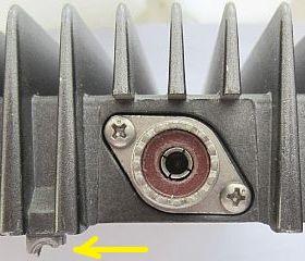
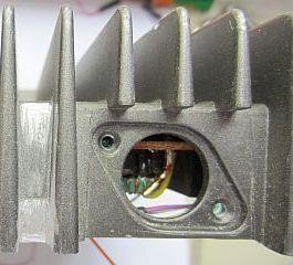
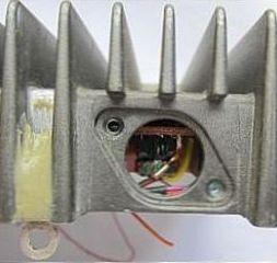
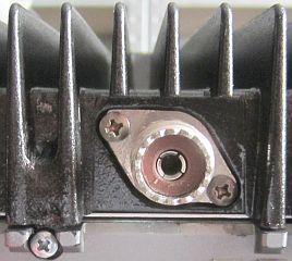
Grinding away the broken pin, then glued with Power Glue and finally sprayed the cabinet with black hammer finish paint. For this, a sprayer is used.
Some of the mounting lips (= cooling block) were broken away. As an experiment, I found it possible to repair them successfully later. For this purpose, solid brass solder cable clips were used. To make place, first the remaining material was grinded away and then the cable lips where glued to the cooling block with two-component glue.
However, observe the long curing time of the glue!
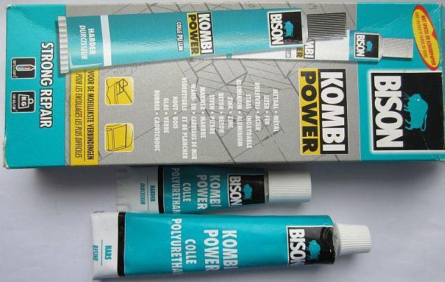
The glue was BISON's KOMBI POWER type. That is a very strong glue type that also can withstand at least 100 °C.
Years ago, I repaired a defective plastic cover for the softening salt in a dishwasher with this glue. After that, the machine has been used for 10 years daily, with the repair being maintained!
Since then, the glue has been applied to me by virtually any common practice.
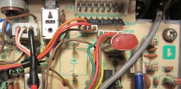
FC-757AT
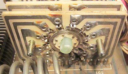
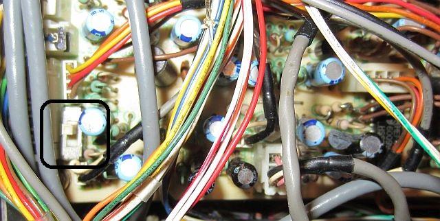
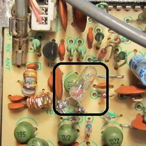
Both of the two FC-757AT antenna tuners I received, where defective. It was found that at the first one SWR measurement was wrong, and the plates of both variable capacitors showed burned spots due to spark surge. At the second tuner some contacts were burnt from a switching wafer (fig»).
In addition, the CPU UNIT # was different and numbered "1" and "2", respectively. Both cabinets were thoroughly rusted on the outside. From the two devices a well-functioning unit was assembled and the cabinet was derusted and sprayed with black hammer finish paint.
FT-757GX(II) ![]() FC-757AT KABEL
FC-757AT KABEL
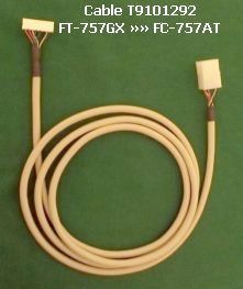
Cable T9101292 is replicated and delivered by Crispino I5XWW upon request.
If you own an automatic antenna tuner FC-757AT then cable T9101292 is required for FT-757GX / FT-757GXII control. In many cases, with a 2nd hand FC-757AT the cable is missing. Frequently asked questions are also asked on forums. Fortunately, after long searching, I found out, that Italian guy I5XWW makes all kinds of cables on request or has them already in stock for well-known amateur devices.
His webpage is http://xoomer.virgilio.it/i5xww/
CR-2025 BATTERY REPLACED
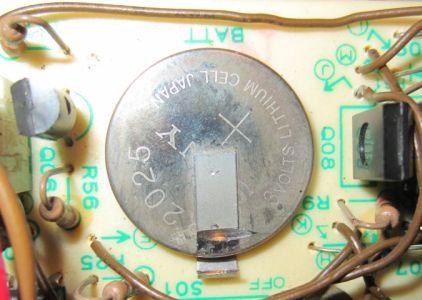
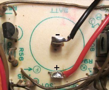
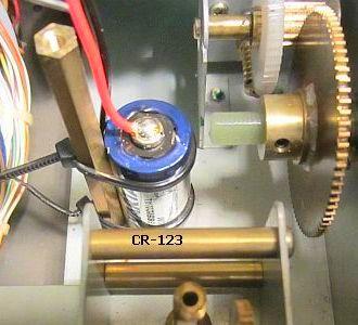
Button Cell CR-2025 is replaced with CR-123 photo battery and attached with cable ties to a vertical stud of the CPU UNIT.
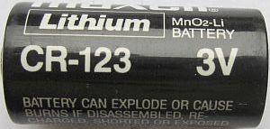
Backup battery CR-2025 has to be replaced over time. In my place of residence, the original type with soldering flaps is not available, but a more common and larger CR-123 photo battery. To shorten the pins as little as possible, a Dremel was slipped through the button cell connections. The remaining upright lips are then suitable for connecting the photo battery with two extension wires. There is room under the CPU UNIT and with two cable ties it can be firmly attached to a vertical stud.
![]()
OE3RDW thanks for this translation!
