![]()
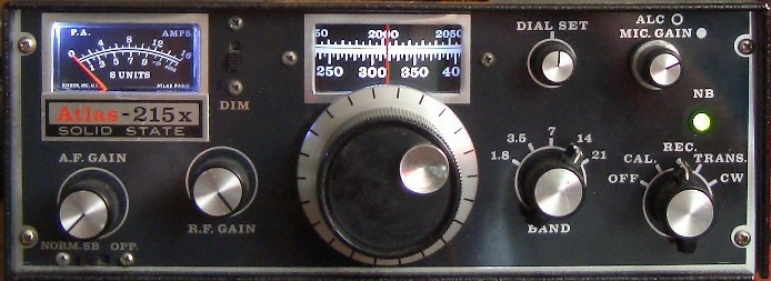
Atlas -210x/215x using X-Lock VFO stabiliser
![]()
CUMBRIA DESIGNS X-Lock VFO Stabilizer.
INTRODUCTION
The free running VFO's in old or vintage rigs are subject to frequency drift due to temperature variations. To cure this I used PAØKSB's VFO stabiliser for a FT-7 and a Corsair II with PAØCMU's print board design.
|
Full size |
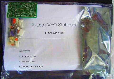
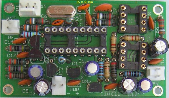
Unfortunately the size of the board was too large for an Atlas. The X-Lock VFO Stabilizer kit (fig») offered by
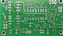
Cumbria designs is an improved version of (SK) PAØKSB's Huff and Puff stabilizer. I ordered and tested this relatively cheap and professional design. This compact 35 × 60 mm module is complete with all components, sockets, and connectors, pin header connectors, PIC processor and a double-sided PCB. The specifications of the manufacturer were confirmed during the test. Finally I mounted it in an Atlas-215x.

|
|
Testing the X-Lock system for function and stability. Prior to reinstallation the board is sitting on the table. The result was excellent. X-Lock held the VFO rock steady during a 12-hour test period. |
INSTALLATION
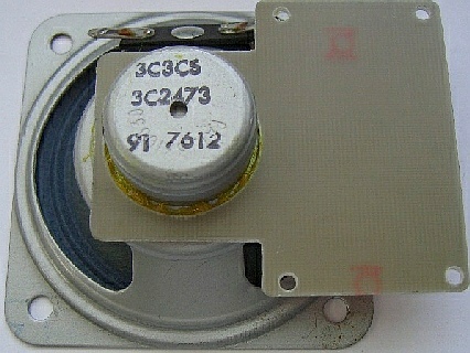
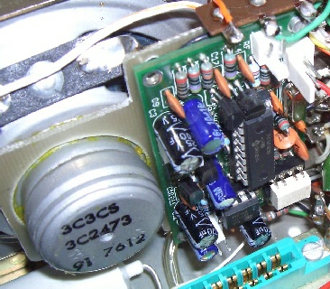
This is a small PCB that I made to mount the X-Lock board. The PCB is glued to the speaker with contact adhesive.
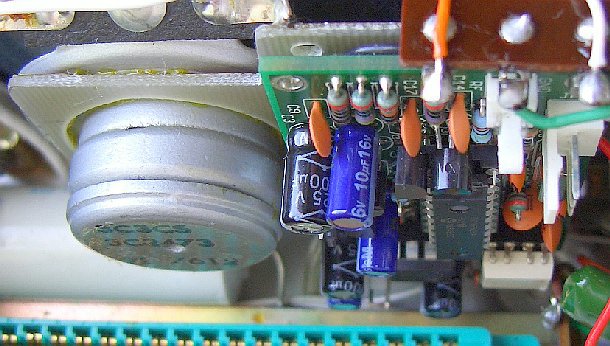
Final installation, because there is little space left over the pin header connectors were not used.
|
|
|
(1) The assembled X-lock board is held in place near the Ext. Osc. socket. For more space eventually replace the speaker with a type of less overall dept. The RF input should be taken from the pins 2 and 3 of the socket. If the VFO's output is to low use the BC547 pre-amplifier. I used this extra amplifier in my Atlas because if I did not, the slight loading change on the VFO, when going between RX - TX - RX, was enough to cause a slight jump (± 10 Hz) of the frequency on a couple of bands.
|
The varicap mounted inside the VFO enclosure. |
|

(2) Open up the VFO enclosure and locate on the tracked side of the VFO board PC-400/PC700 the junction of emitter resistor R404 and capacitor C403. The circuit configuration is show in the schematic, very carefully solder the four parts. Solder one leg of a 10 nF capacitor to the junction and use C426's soldering tag for the other three parts. Mount a wire from the VAR connector to the components.
(3) If required the three-colour LED may be remotely fitted to the front panel. Find a suitable place for the LED and connect 3 wires to the LED connector. I mounted the LED in the (empty) hole for the noise blanker.
(4) Connect the PWR socket to the 13 V DC rail inside the Atlas.
That's all. If you assembled the board correctly the device should worked straight off on power up!
|
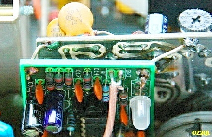 |
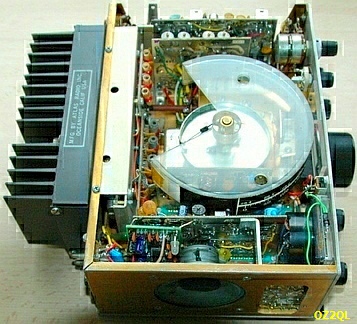
OZ2QL
mounted the X-lock in an Atlas-210x. It works just fine, but his rig has another VFO with two FET transistors on the board. He used the supplied LED "varactor" and a 2.5 pF capacitor connected directly to the dial capacitor. He also mounted the same set-up in his Atlas-350-XL.CONCLUSION
The device is an easily applied "add-on" module and the ability to detect rapid frequency changes during transmit and receive is a valuable innovation. It does exactly what is published in the advertisement and the Atlas-215x is astonishingly rock steady like a crystal controlled oscillator. I am very enthusiastic about this X-Lock kit and can recommend the Cumbria design.
IMPROVEMENT
A Ham wrote:
"I have followed your suggestion and installed the Cumbria designs VFO stabilizer in my Atlas 210X LE with very good results. There seems to be a little problem though which you also mention in your original article, and would like your advice: When going from Rx to TX there is a temporary unlock of the stabilizer (as indicated by its indicator LED going temporarily to red) before locking again. When on a specific operating frequency, on the first transmission the TX lock delay is the one set in the stabilizer (2 sec by default), and on subsequent Rx Tx cycles, the lock becomes instantaneous but the temporary unlocking remains.
The problem with the above is that during the short Rx-Tx unlock cycle, the stabilizer locks at a slightly (20 - 50Hz) different frequency than the one selected during Rx, which results in reports of being "off frequency" from people on the receiving end of the QSO. Since during Rx the VFO returns exactly to the originally selected frequency as before Tx ing, there is no way one can predict where exactly his Tx frequency will end up or correcting for the offset.
Probably the stabilizer after being temporarily unlocked when going from Rx to Tx, "grabs" at a new slightly different frequency and then treats it as a RIT offset and reproduces the initial Rx - Tx error during the following cycles.
A similar behaviour is NOT observed in my Drake TR-7 where the same stabilizer circuit is installed, and it remains in its locked state during Rx-Tx cycles, without any offset frequency problem at all.
For some reason, the Atlas VFO is subjected to some kind of some (?) loading during Rx-->Tx-->Rx which is instantaneous but enough to unlock the stabilizer and create the above issue. Have tried installing the VFO one transistor amplifier per your suggestion, but it did not change this pattern.
I was wondering if you have experienced a similar problem and have thought of any remedy that could be used".
My reply:
I have experienced a similar problem and have been thinking about a possible cause and remedy that could be used. The VFO is probably temporary unloaded during the short Rx-Tx cycle, but the period is apparently sufficient to activate the stabilizer. Hence the extra VFO one transistor amplifier in front of the stabilizer does not change this pattern. (I use this BC547 amp for more signals to the stabilizer). Without the stabilizer (the original set up) the Tx frequency "turns" back to the Rx frequency.
I have not tried it yet (no spare time), but I think an extra buffer × 1 amplifier directly behind the VFO will be an improvement (?).
Then we were both doing various tests to find the problem and he discovered:
"Finally tonight following your message I got around to doing some testing myself. And here goes the saying that no theory is safe without the experimental confirmation!
Connected both my 210x units as follows: The 210LE (lets call it slave) with the stabilizer installed was controlled by the VFO of the other 210M (master) unit via the accessory plug. (both the VFO jumpers were removed and the output from the 210M VFO connected to the input of the 210LE via RG-173).
Here comes the interesting result:
So the conclusion: VFO temporary loading or power surge of some kind is responsible for the symptoms. NOT vibrations from the relay, since if that was the case, activating the Tx relay in the master rig would have to result in temporary unlock". If the relay vibration theory was true, the results of the above experiment would be expected to be exactly the opposite...
My reply:
|
|
|
I did not mention it in my previous emails, but a 2N3866-transistor buffer is installed within the closed VFO chamber (fig») and a 9-Volt regulator outside near the VFO box. The 1 stage BC547 "VFO preamp" of my original article was already removed.
Two days ago I also discovered that the relays are not the problem. I removed PC300 and PC100 with NO flashing of the LED to red. I replaced the PC300 and the LED flashes to red. So the problem was the PC300 board.
What I found yesterday afternoon:
- Insufficient isolation between the VFO and the FET switches on the PC300 board.
- A power surge on that board via pin 1 (= "T" LINE).
Remedy:
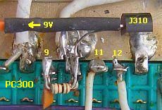
- An extra J310 unity gain buffer amplifier (fig»).
- A 100 µF capacitor across pin 1 and ground on the PC300 board.
The positive result:
The stabilizer kept functioning with NO flashing of the LED to red (on all bands)!
See the schematic.

INSTALLATION
|
|
|
1. Install the 2N3866 amplifier in the VFO box.
2. Connect a coax cable from terminal 3 of the 9 pin Noval socket (labelled Ext. Osc.) to the input of the J310 unity gain amplifier.
3. Connect a coax cable from the J310 amplifier to the input of the stabilizer.
4. Disconnect the wire from the VFO to the original regulator line.
5. Install an extra 9-Volt regulator (fig») and supply 9-Volt to the VFO and unity gain amplifier.
6. Solder (fig») a 100µF capacitor across pin 1 and ground on the PC300 board.
In retrospect maybe it was more elegant to have installed all the transistors in the VFO box.
See my other Atlas-210x/215x articles:
General information Post mixer amplifier AGC modification 17 m modification Speech processor![]()