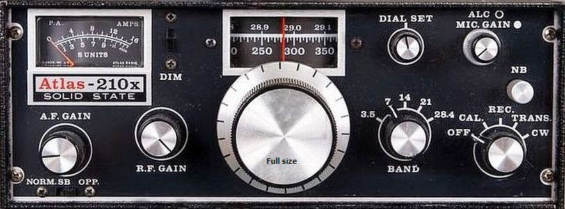
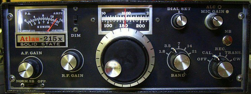
LIMITING HF SPEECH PROCESSOR FOR Atlas210x/215X
A simple (universal) system based on DSB clipping and selection with one filter.
![]()
INTRODUCTION
The DSB limiter in my original article (see
RF speech processor) gave problems for some foreign home brewers. Probably by using a different type of IC (eg TBA120S, TBA120AS, TBA120T, TBA120U) than the previous model (TBA120, TBA120A) which was used in my circuit. Moreover, the older types are difficult to obtain. Reason why I started experimenting with readily available mixer NE612A (or SA12AN). This experimental version («fig) of a speech clipper, one of the many tested designs, worked satisfactorily.
DESIGN
The double sideband signal from the first NE612A (pins 4, 5) is too weak to be limited with two silicon or Schottky diodes without idling current.
During experimenting arose («fig) a clipper circuit with one diode and the emitter-base junction of a transistor (T1) as second diode.

The 1k8 and 3k9 resistors are used for the best possible symmetrical clipping. Eventually can be replaced («fig) by a 5k0 potentiometer and 1K0 resistor to refine symmetrical clipping. The transistor contributes the necessary amplification for the ceramic filter CFW455H. This 455 kHz type must be loaded at input and output with 2k0 impedance, which I did at first. However no marked difference was noted with the higher values in the diagram.
The intention is that the diodes clips and not the second mixer. With sufficient signal from the filter, the second mixer limits rather than the diodes. Therefore the filter is loaded with a voltage divider (2k2, 1K0).

Note that, unlike the designs of others, oscillator and RF signals are respectively routed to pins 1 and 6 of the second NE612A. I did this for more LF output at pin 4.
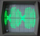
The clipping level is determined by the strength of the microphone signal. Extreme limiting must be avoid to maintain a good understanding. Optimal is a higher average power output while the listener does not notice that a speech processor is in action. The S meter moves much less. This (fig») can be seen on an oscilloscope with aaahhh ... into the mic.
The increased average output is noticeable. Use a 230 V/100 W lamp as transmitter load and tune with an ATU for SWR = 1. Speak into the microphone without processor and then enabled clipper, see the lamp show's more light.
FILTER
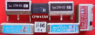
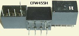
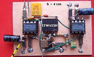
The Murata 6 kHz/6 dB, 18 kHz/50 dB CFW455H filter («fig) is selected as a compromise between bandwidth and price. The type is obsolete, but is still available via internet (ebay.de, ebay.co.uk). More modern versions with the same specifications and with the addition of "H" (eg CFWLA455KHFA-B0) are also suitable. Alternatively, an expensive and narrow SSB filter type CFJ455K13 may used.
RESONATOR
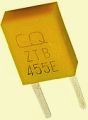
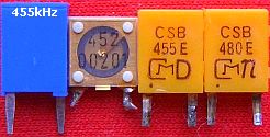
A (fig ») 455 kHz ceramic resonator is used for the oscillator circuit. Unfortunately, they seldom resonate at the specified frequency. Experimentation is often needed even with items of the same type and brand. I chose for a Murata CSB455E, this model is more in circulation. Some vendors offer (fig») a ZTB455E resonator, probably a newer version of the CSB455E type.
Depending on the resonator's oscillation frequency the filter's output signal is SSB with suppressed opposite sideband or partly suppressed opposite sideband. Almost perfect SSB is obtained if the carrier is set to 452 or 457 kHz, which favour to the last frequency. Unfortunately the CSB455E does not oscillate on 457 kHz in this design.
INSTALLATION
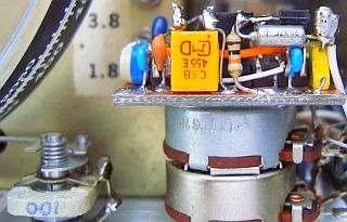
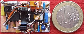
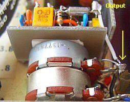
Because the very limited space in my Atlas210x/215x with an already mounted VFO stabilizer, an etched PCB is too big. So I soldered (fig») the components "dead beetle" style on a cladded printboard.
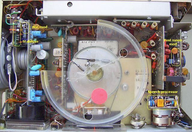
Installation in the Atlas is done (fig») at the back of the MIC.GAIN/ALC pot with double-sided mounting tape.
|
-Desolder at the top of the potmeter the wire to PC300. -Decouple with 10 nF. -Connect the wire via a 47k resistor to the input of the processor. -Connect a wire from the output to the potmeter. -Connect a wire to chassis/ground. -Connect a wire to the (= orange wire) 8-9 Volt supply. |
|
See my other Atlas-210x/215x articles:
![]()