Atlas-210, Atlas -210x, Atlas-215x Information & Modifications

By owning several Atlas transceivers I have gained over the years practical experience about their habits. Installed modifications were removed or replaced by another. Therefore my previous articles were rewritten and more complicated modifications reinstated as a separate topic.

See Atlas-210x/215x:

VFO stabilizer

AGC Modification

Post mixer amplifier

Speech processor

17m-band modification

INTRODUCTION

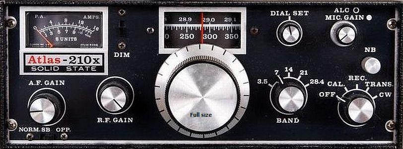
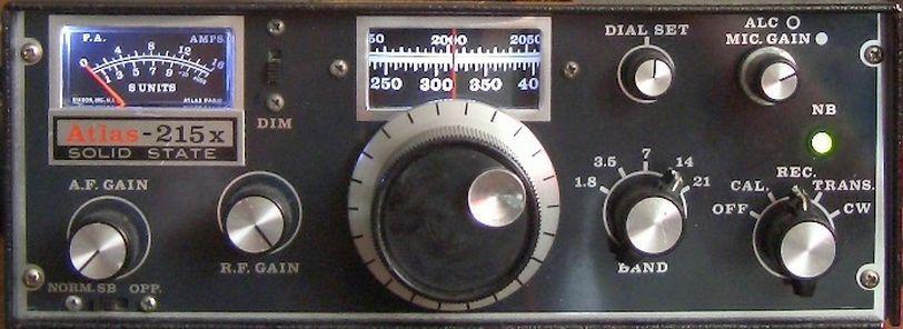
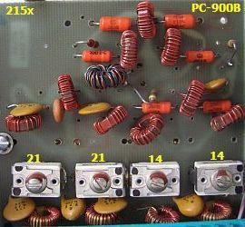
Over the years I purchased via eBay or flea markets Atlas-210, two -210x, -215x and a discarded -210x. The advantage of all purchases is that I have access to various types of A, B, C and D PCB's so that comparison is possible. A good opportunity to get more insight into developments that have been applied.

Atlas products are suitable backup transceivers, simple structure, easy to operate, repair, or modify. By the use of plug-in boards, one can test their own ideas or temporary or permanent installs a modification. The sets have a quiet receiver without a preamplifier and as receiver only consume 150 mA with standard illumination switched off. With installed LED's the total power consumption is only about 160 mA! Peanuts compared to modern sets with there at least 1000 mA power consumption in standby! In case of emergency you at least can operate SSB twenty-four hours from a hefty car battery.

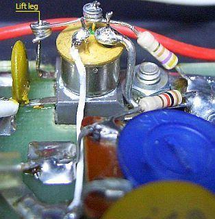
Cons: Not designed for telegraphy, probably because US hams use mainly SSB. Operate with CW works but is cumbersome. AGC can be better and several owners are faced with blown PA transistors, probably due to oscillation of the output stage or a high ambient temperature. Hams use the set in their cars driving in sunny states.

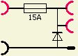
Almost all schematics in my Atlas articles are drawn with sPlan.

General Information, Recommendations and Simple Modifications

This article was written with the following objectives: general information, recommendations and simple modifications. Descriptions of complex changes are published in separate articles. All Atlas models works well when they are adjusted correctly. Here proposed changes in circuits are not absolutely necessary. Judge for yourself what you want to apply or not. It may be necessary to resolder joints, especially VFO's band switch. Almost all the modifications made by me are arranged in such a way that the original designs easily can be restored with minor damage. Some circuit changes may have been superseded by official updates without proper updates of schematics

INSTALLATION OPERATION AND MAINTENANCE DOCUMENTATION

Atlas has never been consistent in correct numbering of components in their diagrams. The same components were renumbered in newer schematics. Modifications were not always updated in their INSTALLATION OPERATION AND MAINTENANCE manual. Added or omitted components were "forgotten" to draw, so PCB's does not match shown schematics.

Sloppy Atlas work: One PC-200C was according to the schematic, the second PC-200C was installed with updates. Two with PC-300C marked circuit boards have different schematics. Furthermore, PC-300A tracks were numbered with 1 - 22 and in a newer manual same tracks of PC-300C are numbered 22 - 1! In my Atlas-210 at PC-100A were two 4.7 Ω resistors mounted instead of 4k7, a factor of 1000 difference! In another Atlas resistor 6k8 was installed instead of 820 Ohm.

The foregoing makes discussing about components not easy because one does not know which version a reader own. Compare diagrams and circuit boards thoroughly if you want to make a change. Do not worry: all previous or later PCB's can be exchanged in any Atlas-210, Atlas-210x and Atlas-215x!

DIFFERENCES BETWEEN MODELS

If the frequency is disregarded, an Atlas-210 is an older design than an Atlas 210x or 215x Atlas. Model 210, for example, is missing SWR protection of the output stage and S-meter scale has a different color and range. Older Atlas models have another VFO circuit. The centre frequency is 5520 kHz, but newer versions were equipped with a 5645 kHz IF filter. Model DD-6B/C Digital Dial (fig») is only suitable for an IF of 5645 kHz. Model DD-6C, however, can be programmed for both filter systems. Later circuits were changed in detail. Receiver input tuning and transmitter input tuning were partly replaced by fixed toroid circuits. Also absorption circuits were added. In later versions, the toroids of the mixers were mounted on sockets and scale range 0 - 350 kHz was extended to 0- 500 kHz. These models have suffix "-x".

ATTENTION!

If the transceiver is switched off the full supply voltage still applies to PC-100/120 and PC-500. Only the rest of the transceiver is turned off. When you experiment, working with battery, remove or install a PCB dismantle the power cable to the supply unit.

When the slide switch on the front panel is in the "OPP" state there is no output in the CW mode (carrier). Convince yourself of the correct position of the switch before you think that the output stage is blown!

CONNECTOR 12 V–13.8 V


The connector for the power supply is designed for insertion into a console where in fits automatically for necessary connections. The possibility was examined whether if on another type DC plug could be used. At the back was not enough space because mechanical work would cause to much damage. I ended up with U-shaped aluminium with fuse and protection diode. The advantage of this circuit is the original system can remain at the back. In the figure you can see gold coloured diode and blue 15 A fuse. This combination is a known system for mistakenly reversed polarity of the supply voltage. If this happens, short-circuit current through the diode blows the fuse. Such protection seems unnecessary but during experimentation you are tense and curious about the result. Then a wrong action can happen, and I speak from experience because once I inserted black plug into red bus.

REMOVING OR REPLACING VOLTAGE REGULATOR


A portion of the transceiver, inter alia, the VFO, is stabilized by a zener diode with emitter follower as voltage regulator. Later versions («fig) used a 3 terminal 6 V voltage regulator with a 2 V or 3.6 V zener diode as voltage boost. Diagrams show 8 V to 10 V, depending on the production date. Diode's can be a significant source of noise that increased by amplification of the regulator. As precaution («fig) the system was decoupled with some 100 nF capacitors. Once I had a QSO with a sailor. He used power from a battery and his Atlas had a trace of FM modulation. Now it is clear why because the regulator needs a supply 3 V higher than the stabilized voltage e.g. 3 + 6 + 3.6 = 12.6 V. During the peak of its modulation, the battery voltage drops below that level. Therefore it is better to replace (fig») by a 3 terminal 10 V low drop regulator type such as L4940V10.

REPAIR FREQUENCY DIAL DRUM

Often the socket screw of the frequency dial drum is screwed too tight so that plastic cracks in several places. All five drums that were examined here showed hub cracks and main body cracking. An outside 22 mm diameter collar cut from a heating pipe will fit necily (fig») around the hub's about 18 mm outside diameter. The collar should be as long as the hub and glued around the hub with two-component adhesive. Tap a 4 mm screw hole in the collar and hub. Use that hole for a new screw. The dial drum can be firmly attached to the shaft and the new construction prevents further cracking of the plastic.

With correct mounting of the drum on the shaft, the frequency scale corresponds well with the actual frequency. Experiment with the distance between the red marking on the front plate and the zero mark on the drum. Do not forget to calibrate the frequency dial wit the slugs of the VFO tuning filters. After adjusting of only directly accessible components, the receiver was sensitive, dial frequency and crystal calibrator were correct. With some practice, tuning with an accuracy of less than 1 kHz is feasible. The VFO drift about 400 Hz at start up, after a half an hour warm-up period the frequency stays quite stable at room temperature.

VFO

For each band the VFO frequency range is different. VFO's of my sets were not equal in stability. The Atlas-210x was the best and as good that a stabilizer was not really necessary. The Atlas-210 was second in terms of stability and a loaned Atlas-215x in third place. However, my own Atlas-215x was a little better than the -210x. Meanwhile, more experience was gained and it turned out that mechanical instability caused VFO instability. The contact resistance of VFO's bands switch determines frequency stability. Further the wire («fig) to the trimmer DIAL SET may cause instability. Improvement in stability was achieved by resoldering the wire at the trimmer, in the VFO box and all soldering tags of the bands switch.

Arrived at the turn of the band switch («fig) in my set beside the marked wires to the flattened shaft. That caused a slight change of capacity so almost always audible frequency was shifted as quickly became the one to the other band switched. Bend is reduced considerably the wires so that they never have contact with the shaft and capacity. When I turned the bands switch the flattened shaft lifted the marked wires. That caused a slight change of capacity and so a frequency shifts. Bend the wires to avoid contact with the shaft.

Standard procedure for me is to apply (fig») contact grease or contact oil on all switches with a small brush. Due to all measures mentioned the VFO is stable at room temperature. As an experiment a Huff and Puff VFO stabilizer was later installed and a separate article is written about.


ADJUSTMENTS LSB & USB OSCILLATOR 5520, 5523.3 kHz


Image on my spectrum analyzer, filter loaded with 1 kΩ,

The IF crystal filter is a very good 8 pole ladder type. DJ9PK has measured the band width of a disassembled Fa. W. van Buuren Phoenix, Arizona filter. His findings are broadly in line with the graph in "INSTALLATION OPERATION AND MAINTENANCE" documentation. A quick measurement with my spectrum analyzer, yielded approximately the same image. My filter was loaded with 1 kΩ at input and output.

According to the manual carrier frequencies 5520 kHz and 5523.3 kHz must be trimmed with respective C603 (NORM. SB) and C602 (OPP.). By listening to a general coverage receiver one can adjust the frequencies for in a clearly audible zero beat. Make a pick up loop («fig), connects the coaxial cable to the receiver and keep the loop close to the oscillator.

Extensive experiments showed that with the Atlas adjustment procedure the best of LSB and USB sound quality was obtained. Use a audio generator with constant output and set to a maximum of 30 mV. Connect a 50 Ω dummy load or a tuned antenna system.

Adjustments are: turns MIC. GAIN and ALC to zero and set the slide switch on the front of NORM. SB. Inject on the lowest band a 1500 Hz signal at the microphone input on the back. Adjust MIC.GAIN and trimmer C603 for 40 W output. Inject 300 Hz and adjust the trimmer for 10 W output. Go back to 1500 Hz and check if the output is 40W. Rule if the LF control signal so that at 40 W output is again. Make sure there is at 300 Hz for 10 W or rule again with C603. Repeat all around until 40 W coincides with 1500 Hz and 10 W at 300 Hz. The slide switch is now in the position OPP and now follow the same procedure with trimmer C602.

If it's good will when switching from NORM. SB OPP to the timbre of the noise sound alike. In practice, the filter does not always seem to be as was shown in the manual. Symmetric In a number of filters removed from the chassis, I also noticed that. With a spectrum analyzer An adjustment of 1550 Hz and 280 Hz was sometimes necessary to adjust. Better with my voice


Na uitgebreide experimenten bleek dat met een Atlas afregelprocedure de beste gelijkheid in draaggolf onderdrukking van LSB en USB verkregen werd. Gebruik een LF generator met constante output en stel in op maximum 30 mV. Belast de zender met een 50 Ω dummy load of een aangepaste antenne.

Het gaat als volgt: draai MIC. GAIN en ALC op nul en plaats de schuifschakelaar aan de voorkant op NORM. SB. Injecteer op de laagste band een 1500 Hz signaal in de microfoon ingang aan de achterkant. Regel met MIC.GAIN en trimmer C603 zodanig af dat het zendvermogen 40 W is. Injecteer nu 300 Hz en regel de trimmer af op een zendvermogen van 10 W. Ga terug naar 1500 Hz en stel vast of de output nog 40 W is. Regel eventueel het LF stuursignaal bij zodat er weer 40 W output is. Controleer of er met 300 Hz nog 10 W is of regel dat opnieuw af met C603. Herhaal alles net zo lang tot 40 W samenvalt met 1500 Hz en 10 W met 300 Hz. De schuifschakelaar gaat nu in de stand OPP en volg nu dezelfde procedure voor met trimmer C602.

Als het goed is zal bij het overschakelen van NORM. SB naar OPP het timbre van de ruis gelijk klinken. In de praktijk blijkt het filter niet altijd zo symmetrisch te zijn als in de handleiding afgebeeld werd. Bij een aantal uit het chassis verwijderde filters heb ik dat ook met een spectrumanalysator kunnen vaststellen. Een afregeling met 1550 Hz en 280 Hz was soms nodig om beter bij mijn stem te passen.

TRANSCEIVER ALIGNMENT

PC-100

PC-100

PC-100

PC-200

Omdat deze transceivers kennelijk met zo weinig mogelijk componenten ontworpen werden, zijn veel delen van de schakeling zowel voor zenden als ontvangen in gebruik. Dat is zeer economisch maar heeft het nadeel dat een verandering ook elders te merken is.

Een (fig») Atlas modificatie op PC-100 was een 100 Ohm (R101) regelweerstand vervangen door een 500 Ohm type met parallel eraan twee in serie geschakelde 68 Ohm weerstanden. Meestal is dat niet in het schema terug te vinden, maar werd het wel op PC-100… printen aangebracht. De wijziging was voor een verbetering van de draaggolf balans. Het is aan te raden om deze modificatie op oudere PC-100 printen aan te berengen. Vervang eventueel R104 door een 1 kΩ trimweerstand. In latere versies van PC-100 blijkt dat een vaste weerstand van 330 Ω kennelijk toch een juiste keus was, zodat u waarschijnlijk geen trimpot hoeft te plaatsen. Bij sommige PC-100… printen versterkte de 1ST I.F. AMP (2N3866) teveel en dan moest de 330 Ohm weerstand vergroot worden.

Een afregeling doe ik als volgt:

Stap 1: zet de schuifschakelaar op NORM. SB en regel op de 80 m band de draaggolf op minimum met C103 en R101 op PC-100. Verwijder daartoe de microfoon en draai de MIC. GAIN linksom op nul. Sluit de set aan op een dummy load en plaats de mode schakelaar in de stand TRANS. Beluister op een ernaast staande ontvanger de draaggolf en lees de S-meter af. Draai nu beurtelings aan C103 en R101 net zolang tot de S meter niet meer lager komt. U kunt ook de draaggolf zichtbaar maken op een scoop en afregelen op een minimum balk. Zet nu de schuifschakelaar op OPP en zie of de S-meter hetzelfde aanwijst. De bedoeling is dat u met het afregelen ervoor zorgt dat in zowel LSB als USB de S-meter of de balk op de scoop hetzelfde aanwijzen.

Omdat de output van de VFO op elke band anders is, zal de rest draaggolf niet overal gelijk zijn.

Stap 2: verwijder de dummy load, zet de bandschakelaar op 14 MHz, de mode schakelaar op CAL en draai de schaal naar 14.200 MHz. Zoek het signaal van de calibrator op en lees de eigen S meter af. Draai nu aan de kern van L103 op PC-100 en regel af op maximum aanwijzing van de S meter.

Stap 3: als R104 op PC-100 vervangen is door een trimweerstand, ga dan als volgt te werk: geef met een meetzender een S9 (50 µV) signaal en draai daarna de RF GAIN volledig tegen de klok in terug. Regel nu R104 af op minimum uitslag van de S meter.

Met een scoop kunt u het anders doen. Bekijk het SSB signaal en draai de MIC. GAIN op maximum. Met het flink blθren in de microfoon zult u geen of bijna geen dynamiek zien. Regel R104 af zodat er ook duidelijk pieken in de modulatie te zien zijn met weinig of geen begrenzing (clipping).

Stap 4: de invloed van spoel L201 op PC-200 kan op elke band weer anders zijn, vooral op het uitgangsvermogen bij 10, 15, en 20 m. Zet de mode schakelaar op CW, de bandschakelaar op 21 en de schuifschakelaar op NORM. SB. Draai de MIC. GAIN op maximum en lees het vermogen af op uw dummy load of op de meter van uw set. Draai de MIC. GAIN zover terug dat de output net terugvalt van maximum. Regel nu de kern van L201 af op maximum output.

Voor het afregelen maakte ik een trimsleutel (fig») van een staafje kunststof. Tussen duim en wijsvinger en wat gepriegel kan ermee aan de kern van L103 gedraaid worden.

Grote invloed op AGC, ALC en de S meter heeft de waarde van R15 («fig) op PC-300. Deze weerstand heeft niet op alle typen PC-300 dezelfde waarde. Een weerstand van 1.5 kΩ voldeed bij mijn apparaten goed. Bij latere printen werd door Atlas een regelbare weerstand gemonteerd.

AFREGELEN PC900


Atlas-210, PC-100A


Atlas-210x, PC-900B

Extender board.

Atlas-215x, PC-900B.

Hier ziet u de "slordigheid" van Atlas: twee maal hetzelfde type nummer PC-900B van de print, maar beide wel verschillend in schema en opbouw.

Het afregelen van PC-900 (Transmitter Input Tuning) kan met een spectrumanalysator gedaan worden. Zelf regelde ik af op maximum zendvermogen in het midden van een band. In een later stadium werd afregeling herhaald met behulp van een spectrumanalysator. Het bleek dat de voorgaande methode goed bruikbaar was.

Bij print PC-900A ontbreekt het bandfilter voor de 10 m band want dat zit bij mijn Atlas-210 op het chassis ("PC-900A") gemonteerd tussen het kristalfilter en PC-900A.

Toegang tot PC-900 voor het afregelen van bandfilters heeft men door het tijdelijk aanbrengen van een haakse "extender board" voor het omklappen van PC-100/PC-120. Dat had ik aanvankelijk niet, maar jaren later kon het zelf gemaakt worden na het verkrijgen van de juiste printconnector. In het begin werd de klus voorzichtig geklaard met een chirurgie tang als trimsleutel.

PC-500/520 RUSTSTROOM INSTELLEN

G3YXM's methode om de ruststroom in te stellen.


De instelling van de ruststroom in deze eindversterker heeft het nadeel dat het nogal temperatuurafhankelijk is. Vaak ook kunnen vele van dergelijke eenvoudige schakelingen niet de gewenste basisstroom leveren als de versterker volledig uitgestuurd wordt. Het gevolg is dat er een min of meer klasse C instelling ontstaat en zo'n PA niet meer lineair werkt. Een beter ontwerp dat gewoonlijk door mij gebruikt wordt is te zien in het artikel HF PA met VHF. Als dat stabilisatie systeem in de Atlas komt, moet er behoorlijk aan de originele printontwerp gesleuteld worden. Een andere schakeling afkomstig van G3YXM's site werd getest en deed het goed. Na bestudering van de PC-500 print bleek (fig») dat er een mogelijkheid was om zijn ontwerp aan te brengen zonder printsporen te veranderen of te beschadigen.

De basis van de regeltransistor Q506 (2N5490) moet los gesoldeerd worden van het printspoor. Buig het pootje naar boven. Het printspoor wordt nu massa gemaakt door dat met een draad aan een massapunt te verbinden. Soldeer de aansluiting van de twee diodes (D501 & D502) los en verwijder een eventuele 100 Ω weerstand van het printspoor. In mijn originele schema ontbreekt deze weerstand maar hij was wel op de print gemonteerd parallel aan de in serie geschakelde diodes D501 en D502. De aansluiting wordt daarna aan de andere poot van de potmeter gesoldeerd. De extra PNP transistor (2N2905 of een ander universeel type) werd omgekeerd op Q506 gemonteerd. Om beide halfgeleiders op gelijke temperauur te houden heb ik voor de zekerheid koelpasta aangebracht. Door montage aan de andere componenten wordt de transistor op zijn plaats gehouden.

Met de bijgevoegde afbeeldingen zal het voor de meeste nabouwers geen probleem zijn om de modificatie aan te brengen. Voor de duidelijkheid zijn twee ontkoppelcondensatoren (10 nF) in het montageplan en op de foto weggelaten. Meestal is bij het opwarmen van de eindtorren een nog betere stabilisatie te bereiken door voor een goed thermisch contact de diodes (D501 en D502) op Q504 en Q505 te monteren. Breng koelpasta aan voor een optimale overdracht van de warmte. Omdat met G3YXM's schakeling de ruststroom verrassend stabiel bleef bij het warm worden van het koelblok, werden de diodes niet verplaatst. Het vermoeden bestaat dat er een temperatuur stabiliserende werking ontstaan is door het omgekeerd monteren van de PNP transistor op de originele regeltransistor Q506. De laatste volgt via het koelblok de temperatuurveranderingen van beide eindtransistors. Met deze stabilisatie schakeling is de ruststroom ook beter op een gewenst niveau in te stellen.

De ruststroom van mijn PA's werden met ingedrukte PTT ingesteld door het totale verbruik van de set zonder verlichting met R515 af te regelen op een stroom van 800 mA.

Atlas-210, PC-400A 3.5–3.8 MHz (EX 3.7–4.05) MODIFICATIE

Mijn Atlas-210 uit de USA was kennelijk niet voor Europa bestemd want de 80 m band loopt van 3.7 - 4.05 MHz. De schaal gaat van 0 - 350 zodat het 10 m bereik 28.4 - 29.1 MHz is bij 15 m maar tot 21.350 MHz. Met de laatste twee beperkingen kan men leven, maar het 80 m bereik is niet voldoende voor huidige frequentiegebied. De bandcorrectie trimmer op 80 m kon het bandsegment slechts maximaal 50 kHz opschuiven. Na enige probeersels met extra parallelcapaciteit bleek dat voor een correcte schaalaanwijzing er beter met zelfinductie geëxperimenteerd kon worden. Het eindresultaat (fig») ziet u hiernaast. Van de bandschakelaar werd het oorspronkelijke spoeltje naar print PC400 (VFO) vervangen door een (~ 0.5 µH) spoel met 11 windingen van 0.6 mm draad dat eerst gewikkeld werd op een 4 mm boortje. Het spoeltje wordt gemonteerd aan de derde aftakking gerekend van de top van L403. De ingangskringen van de ontvanger (PC900) moeten opnieuw in het midden van de band (3.650 MHz) afgeregeld worden.