KENWOOD TL-922 (TL-922A, TL922) MODIFICATIONS
![]() 13-may-2024.
13-may-2024.
|
|
Click voor minimum modification
9 Bands with 1000-1300 Watt output!
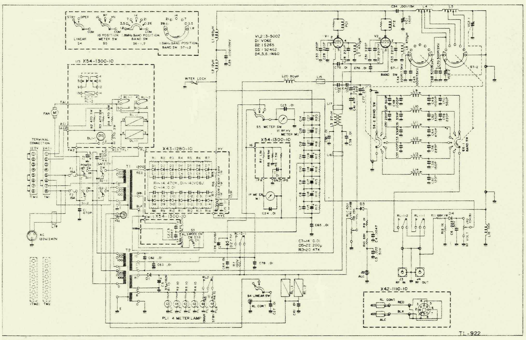
Click on schematic to enlarge.
INTRODUCTION
|
At the top and the bottom of the valves changes were implemented which improve stability. |
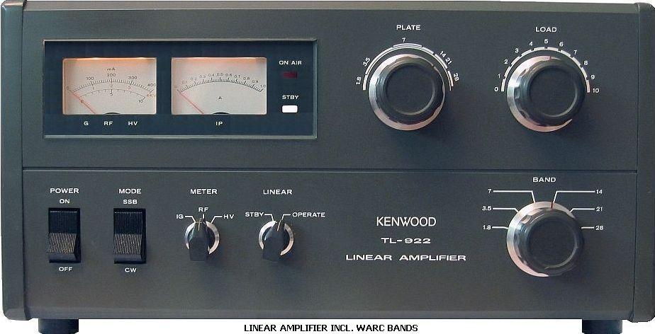
A Kenwood TL922 linear amplifier with 2 × 3-500Z valves is one of the best, sturdiest and compact pieces of equipment for radio amateurs. It is equipped with double shielding in a cabinet of thick material with sturdy handles. It is designed with good quality components and there are separate transformers for high voltage and filaments. If the HV transformer overheats, a thermal safety device incorporated inside it will operate and disconnects the bias. When you switch off the amplifier, the cooling fan will carry on for a few more minutes. Here are features, which are not present in a lot of current models. This is good advice if you come across a 2nd hand one, however there is always room for improvement.
The filaments have the correct heater voltage if the (NL) 228 Volts mains voltage is supplied on the 240 volts connection of the transformers. With a 100 W exciter the amplifier will deliver about 1000 to 1150 watts on 10, 12, 15, 17, 20, 40, 80 and 160 meters into a 50 Ohm termination. One can also transmit quite a bit of power on the 30 m band with a tuner between the exciter and the amplifier. When all grids were directly grounded, the power increased to 1300 watts maximum.
MY OPINION
It is wise to fit the minimum modification at the end of this article before you switch on this amplifier.
REACTIVATON 3-500Z
 To avoid flashover in a new or a long time unused tube, it is prudent to prepare ("reactivate") it for his task. There are various opinions and solutions how to do it, but with a 3-500Z it can be relatively simple. A DC of 30 to 40 V is sufficient for the tube to draw 400 mA as the grid is connected to the anode. Heat the tube 30 minutes with a filament voltage of 4.9 V. Then supply a "high voltage" of about 35 V and set the voltage to a current of 400 mA. If possible use a current limiter, because during reactivate the current can increase suddenly so that continue monitoring could be necessary to maintain 400 mA. Usually I will not reactivate longer than an hour or so. Soon you will find out that a good tube behaves like the showed table.
OUTPUT, LOAD & PLATE SETTING ON 9 BANDS AFTER MODIFICATIONS
After normal tune up of the TL922A, increase the power output of the transciever to full output and readjust the PLATE & LOAD for maximum RF power out of the amplifier. Your grid current (Ig) will be a little over 200 mA so make it quick! During SSB transmission after tuning like this, the Ig meter never deflects beyond 125 mA. Average Ig during SSB is what's important. Peak Ig, which your Ig meter will not read, is not important. During CW tune up I see around 1250 W/750 mA cathode current (Ic) and 225 mA grid current (Ig).
|
|
Maximum performance with about 2 m coax cable. |
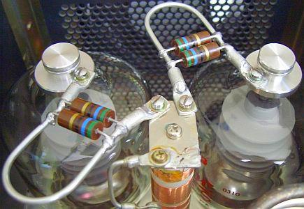
A stable TL-922 was the result after implementing modifications, like the length of the coax cable between exciter and amplifier, all grids direct to ground (no capacitors) and an extra earth wire to VC1. Sometimes during the daytime the mains voltage is a bit higher and the amplifier can give approx. 50 watts more output.
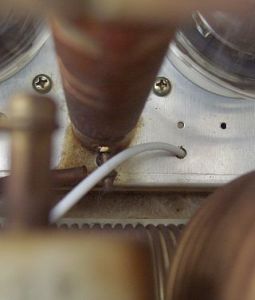
Wire to VC1.
 This modification improves the stability by means of a shorter connection to a common RF ground near the valve sockets. Such a direct connection I have done in all HF amplifiers, for example Yaesu FL2100, Dentron GLA1000, AEA LA30, NEC CQ301, Heathkit SB200, TenTec Centaur and my own designs. This was the cause of oscillations on VHF in a lot of amplifiers.
Richard Measures AG6K fixed this problem with multiple parasitic suppressers, but it is far easier and cheaper to have a direct connection from the plate capacitor to the grid connections on the valve sockets. The ground connection of the variable capacitor is in reality "isolated" from the valve sockets, because it is situated in a kind of Faraday cage.
A RF current from the variable capacitor doesn't arrive at the valve socket via the shortest route. It is possible that with other amplifiers too, this will lead to instability.
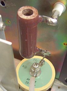
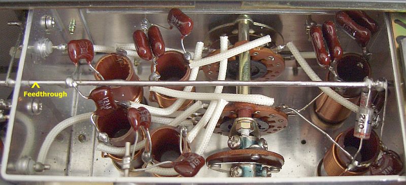
A direct connection from the variable capacitor to the bottom of the valves will prevent this. You can use an insulated wire through a hole already present in the frame. In my own equipment a feedthrough with solder connections was implemented.
|
|
|
|

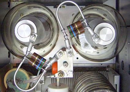
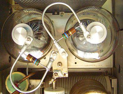
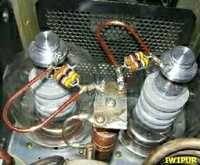
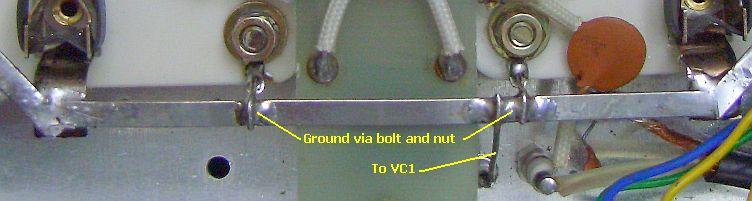
This is the way it was implemented in an amplifier belonging to a fellow ham.
At the bottom you connect the two ground supports, one on each side of the valve sockets, with a length of 2.5 mm² tinned copper wire. This will become the common earth for both valves and the connection for the extra wire to VC1
PARASITIC SUPPRESSION CIRCUITS

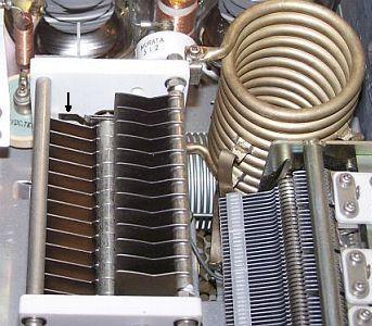
A method of parasitic suppression is the insertion of RF current (hairpin shaped) obstacles (dampers) at right angles («fig) to the probable flow of the parasitic currents. This method can be used up to frequencies of several 100 MHz without noticeably reducing fundamental power. The main function is to provide a high impedance path in series with other (tank) circuit elements. However such method can be used only where the fundamental and parasitic frequencies are sufficiently far apart, so that excessive resistive losses of the fundamental frequencies are avoided. The circuit should have a L/C ratio al low as practicable and be suitably damped to give a broadband effect.
Damping can be achieved by paralleling the hairpin circuit inductor with a non-inductive resistor and by making the inductor from resistive material. A mat surface rather than a polished surface may provide sufficient surface resistance. The resistive component need often be no more than a nickel alloy wire/strip or tinned copper wire/strip with a DC resistive value of a fraction of an ohm.
|
|
|
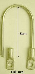
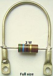
The parasitic suppressers were made from a 12 cm piece of tinned copper 2.5 mm² or 12 AWG wire.
The parasitic suppressors were made from a 12 cm piece of tinned copper 2.5 mm² or 2 mm diameter wire. The resistors of the original dampers looked a bid sad and were cracked, their shape was also in my opinion a bit small.
|
|
|
|
|

 The "ancient" carbon resistors («fig) are almost impossible to obtain, but there are suitable 3 W (PHILIPS) metal film resistors.
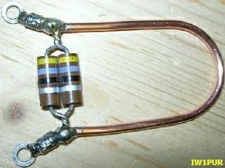
My experience with hairpin parasitic suppressors is that they work better then coiled inductors with resistors in the centre of it. All my amplifiers were done like that, so this one was done the same way. According to Richard Measures AG6K they have to be made of nichrome wire, but that is not necessary.
If you use 6 mm² or 2.7 mm diameter tinned copper wire (fig»), it will have sufficient skin resistance for VHF. They will be as sturdy as the original suppressers. Cut off a 12 cm long piece of wire and bend it around a piece of pipe 25 mm od., solder a lug (eye cable tag) on each end. In the US that size lug is very hard to find, however, WN4N found some made by Burndy. They are available from Graybar Electric the largest supplier of electrical construction in the US. The number is 93157387. The Burndy part number is YA8CLNT6. In the event someone needs to find these lugs you will know where it can be found.
When I think about it, it wouldn't surprise me because the way the resistors are attached, the suppressers could be effective on 2 frequencies.
TO-220 STYLE RESISTOR
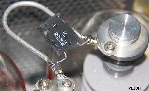

Nowadays it is not easy to obtain conventional non inductive resistors. A considerable number of amateurs ask me for help or advice. Although I have not tested it yet, I suggested («fig) to try it with non-inductive metal plate resistor housed in TO-220 style package. PE1DFT did the experiment. He wrote: "I'd promised feedback and can say: It works, they are almost one year installed («fig) and everything is still intact!"
That's good news for anyone who has to retrofit his PA.
GROUND THE GRIDS ANOTHER WAY.
Note: Each amplifier seems mechanically the same, but that is not electrically. Therefore there is a difference in stability. If you ground the grids directly eventually you have to replace or change the parasite suppressors. Use the hairpin type and if the PA still oscillate, change the size of the suppressors a bit.
|
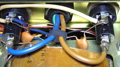
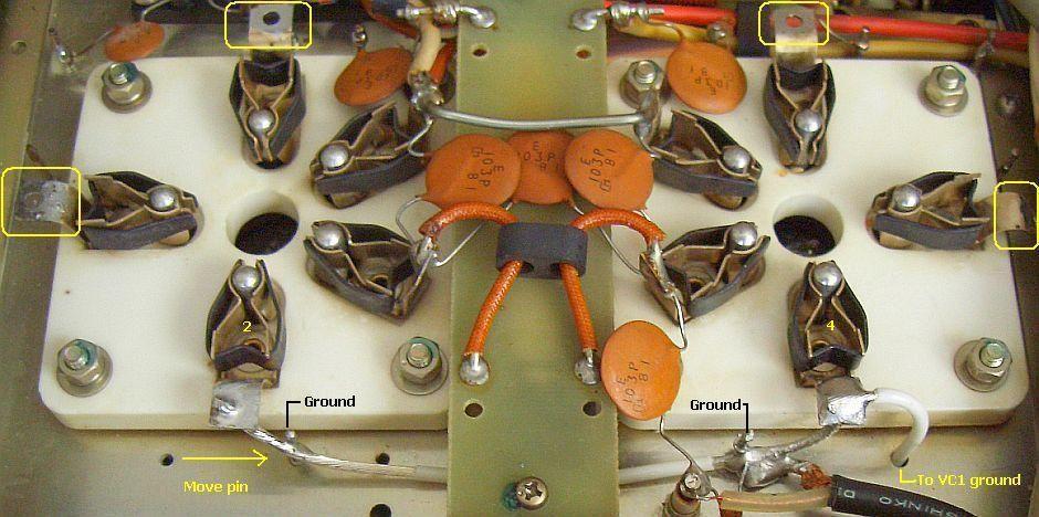
In my TL922 I grounded all grids original with 3 × 220 pf to one ground point next to the valve socket, this point is also connected with an insulated wire to VC1. (At a later stage the decoupling capacitors were removed and all grid connections were grounded.) |
My experience on HF is that it is better to connect all grid pins together and to connect only to one point on the chassis. This way a HF current is forced to go one way only which will enhance stability. When this was applied to a NEC CQ301 amplifier with 2 × 3-500Z, it was cured of instability instantaneously. In a different type of amp the output power increased with 100 watts on the 10-meter band.
 I prefer to remove all decoupling capacitors and connect all grid connections direct to ground. If you do it that way, the input impedance of the valves will change and the input inductors may have to be readjusted to SWR = 1.
The minimal decoupling capacitance of 3 × 220 pf for each valve gives a negative AC feedback that makes the input impedance different then with direct connection to ground
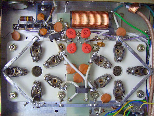
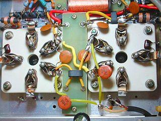
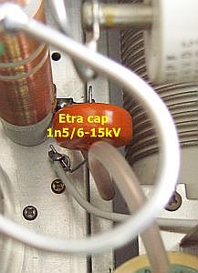
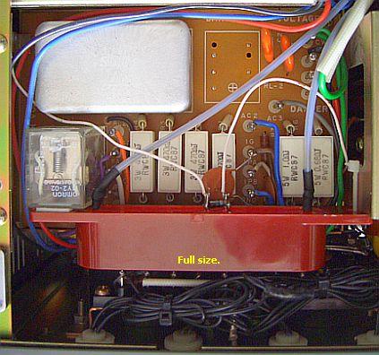
For an improved decoupling of 80 and 160 meters of the anode choke, an extra 1500 pf capacitor was installed and grounded to the feedthrough earth wire. For the same reason a few more capacitors were added across the filament connections. Red caps. See photo.
|
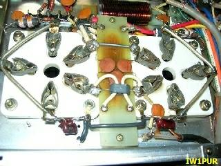
The final modification with C28 - C33, R22, R23, L7 and L8 removed. |
A 12 pF capacitor was added to compensates for the removed voltage divider C40 and C41. |
At a later stage the decoupling capacitors were removed and all grid connections were grounded. Above all expectations it worked very well and output power was increased to 1250 watts on some bands. L7, L8, R22, R23 and components from the ALC were all removed. I didn't use the latter because I never use more then 100 watts.
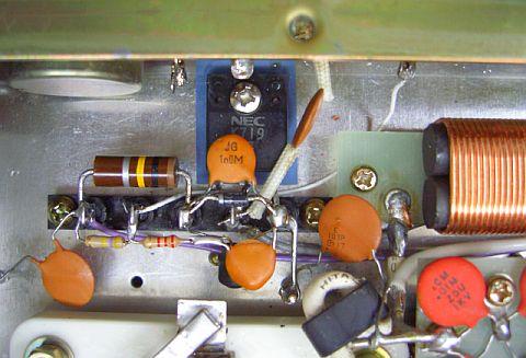
The old mounting strip was used for the new relay circuitry, which appears further down this article. The MosFet of this system is seen as a little black square in the left-hand top of the photo. To compensate for the removed voltage divider C40 a C41, a 12 pf was added.
If I drive my amplifier with a 100W carrier, the control grid current in some bands is more than 200 mA. That is not bad for the tubes because that is on average much less with SSB or CW.
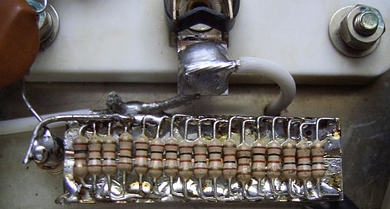
The application of feedback can make things better. This can be achieved with a non decoupled induction free resistor of 5 to 10 ohms between C42 and the coaxial cable to the band switch S6-2. This type resistor is not easy and cheap to buy. However, with quiet a number of "ordinary" 100-ohm resistors in parallel, the total self-inductance for HF is so low that it can be neglected. It is claimed that the resistor prevents random oscillations or suppresses parasites.
CONNECTING THE FILAMENTS DIFFERENTLY
|
A modification of a different Japanese ham with signal on pin 1. |
Different Japanese modification. |
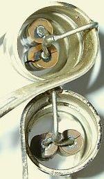
While surfing on the Internet I found the site of JH2CLV which was difficult for me to read, but I understood out of the drawings what was going on. According to this OM it is better due to the mechanical construction of the filament (fig») in a 3-500Z to connect it somewhat differently. This way the input signal appears on pin 5 of both valves instead of one valve on pin 1 and the other on pin 5.
It could also be to reduce 50 Hz hums during an AM transmission or that the "wrong" connection can shield parts of the filament, so they slow down the electron flow. For the rest it isn't very clear, because on another Japanese site (see photo) the input signal is connected to pin 1 of both valves.
Assuming the drawing of the filament gives the correct picture of the real mechanical construction I'm inclined to use pins 5 for the input signal. These can bee seen in the previous photo of my TL-922.
PROTECTION FOR VALVES AND POWER SUPPLY
|
|
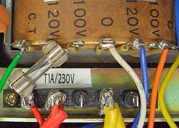
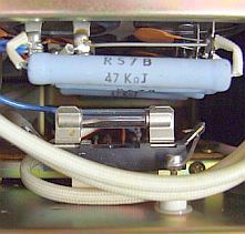
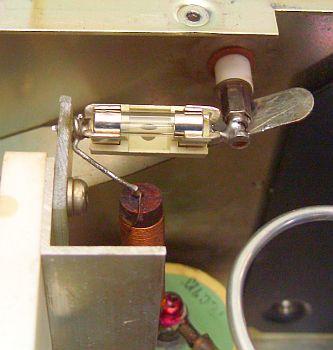
A slow-blow fuse in the primary side of the filament transformer. |
Grid chokes sometimes burn out because of instability of the valves.
That happen more to valves, which haven't been used for a long time.
The short circuit goes via relay R2-1, the zener diode and the frame, the meter also will get a big knock.
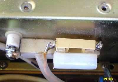
Connecting fuses in series with grid chokes L7, L8, can make a protection. I didn't do this in my TL922, but as a preventive against grid to cathode (filament) short. I connected (see fig») a fuse on the primary side of the filament transformer.
|
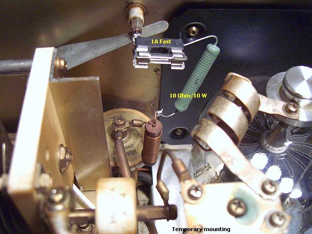
While testing I connected the safety resistor and fuse temporarily and later installed it more permanently (fig») |
I did not use L2 (12 µH).
More permanent construction.
|
We can protect the valves and power supply against momentary shorts (ea. Flashover) by means of a resistor together with a fuse in series with the anode choke. In the photo this was done temporarily to protect and test the amplifier. Later it can be installed more permanently.
During the test a 2nd hand 3-500Z was tested for usefulness. The valve under test wasn't used for a long time. A variable transformer c was connected and the voltage was slowly increased where at a certain point a few flashovers occurred and the 1 Amp fuse was blown. This proved that the power supply was well protected. After about 30 minutes and a few more blown fuses the valve became stable, had his normal output and the plasma glow had disappeared.
INPUT CIRCUIT FOR 10 METERS

Guido ZL2VB (ex NL) wrote to me: I replaced the windings on the 10 meter input coil with 3½ instead of 2½ turns. The adjustable core didn't change the induction in the coil sufficiently to bring the SWR down. Replacing the input capacitor wasn't a good idea because it will make for a narrower bandwidth. With 3½ turns (« fig) and a 120 pf capacitor (C60) the end result was a SWR of 1 : 1.15 at the band edges between 24 and 30 MHz.
The SWR on 40, 80 and 160 meters was very good in the amplifier we tested at the time, but less so on 15 meters and not very good at all on 10 and 20 meters. Please take note, whenever you replace the valves at least on the higher bands, the input coils have to be readjusted. In my own amplifier only the SWR on 80 meters was unsatisfactory. See next chapter.
INPUT CIRCUIT FOR 80 METERS
It was found that in 2 different TL922's it wasn't possible to get the input SWR down sufficiently. This isn't accidentally but a design fault. Even with a variable capacitor instead of fixed ones, the results were not consistent. If there was a good SWR at the start of the band, it was bad at the end or visa versa. Also the length of the cable between exciter and amplifier has an influence on the SWR on all bands.
It was discussed on the Internet that what was ok for one person, didn't work for somebody else. I blame this on variations in the way the input circuits were manufactured (fig».) The circuits are in a Faraday cage and don't allow the RF current to return to ground directly. You can put an insulated tinned copper wire through the hole of where a ground pin uses to be and use this as a central grounding point (left). The best way to do this to ground all capacitors of the input filters on this earth wire. In the meantime this was only done for the 10, 15 and 80 meter input circuits.
|
|
|
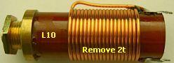
After a bit of experimenting a better compromise was reached for 80 m by removing 2 turns of L10 and to increase a number of the capacitors in parallel to the existing ones (fig »). The range of the inductor was changed from 2.7 – 3.2 μH to 2.5 – 3 μH. If you want a different inductor value, you can calculate this with the formula L(μH) = 9n² χ1000, "n" is the number of turns.
Attention: In the circuit diagram C57 and C59 is 120 pF respectively 220 pF. In my amplifier the manufacturer had a 120 pF capacitor for both C57 and C59!
WITH 2 METERS OF COAX CABLE SWR < 1.5 (also on 12, 17 & 30 meter).
The length of a 50 Ω (RG58) coax cable between exciter and amplifier has a strong influence on the SWR. It seems that after adjusting all the input filters a length of 2 m was the optimum for all bands. That was also favourable for 12 and 17 meters because it was possible to transmit with 1000 to 1100 watts with very low SWR.
When later on all grids were directly grounded, the SWR remained the same and even went down on some bands. Only on the 12-meter band it was worse if the band switch was in the 15-meter position. So it maybe better to use the 10-meter position to get a better SWR on 12 meter.
SUPPLY VOLTAGE AND IDLE CURRENT
 The input voltage of the power transformers can be changed either up to 240 or down to 220 Volt. The present line voltage in the Netherlands is only 228 V. If you set in the 220 V position you get more power-out, but your valve filament voltage is to high. However if you select 240 V, you will have the correct filament voltage of between 4.85 and 4.95 Volts, but your idle current will be to low. This can be corrected with 4 × 3 Amps (1N5408) diodes (in series) parallel to de zener diode D2 (7.5V). Depending on the individual 3-500Z, that could be more or less.
Because both 3-500ZG's are working under the same conditions as the Drake L-4B amplifier (see table), one can use the L-4B idle current for the TL922 without any problems. In my amplifier with 2 × 3-500ZG (RF PARTS) the idle current was adjusted to 190 mA. I also found an Eimac spec. sheet for the 3-500Z that advises 115 mA per valve.
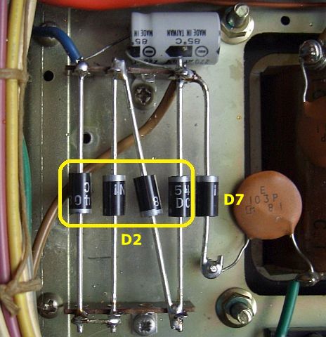
In another TL-922, the previous owner removed zenerdiode D2 with all mechanical components and then mounted 10 diodes in series. That was a rather clumsy and mechanically unstable construction. So everything was removed and replaced (fig») by 4 × 3A diodes (1N5408) in series mounted on supports in two released holes. This lower number was necessary because the 228 V line voltage was set in the 240 V position. The idle current was about 220 mA/2400 V on load.
To prevent mistakes and to keep the wiring orderly, some people have removed the extra wiring for the change to 110 – 120 Volt. Only the 220 – 240 Volt wiring was left. This way one can wire the HV transformer for 220 Volt and the filament transformer for 240 Volt.
ANTENNA RELAY SWITCHING
|
|
When a transceiver excites this amplifier, it has to cope with approximate 80 – 100 Volt to switch the input and output relays of the amplifier. Most modern transceivers are not suitable for high voltage switching.
Typical antenna relay switching outputs for modern exciters are: Open collector transistor or reed relay with voltages of between 12 and 48 Volt maximum and low currents. The circuit, which was used, had already been used in a modified SB200 amplifier.
A transceiver used with this amplifier had to switch only +1.5 volt at 200 µA. A multitude of transmitters can therefore used this way. It is still in the testing stage, but it works perfect until now. Everything is in the spot of the old ALC system (which has been removed). The 2SK719 MOSFET out of my junk box came probably out of the switching power supply of an old monitor. The specifications are Id = 5A, Uds = 900 Volt, P = 120 Watt and Rds = 3 Ω. These specifications are a bit over the top, the most you need is Id = 1A and Uds = 300 Volt. For the transistor any universal type can be used and you can connect a diode across drain and source to limit the peak current.
You can use this with al the QSK modifications of Richard Measures AG6K.
|
ZL2VB's modification. |
|
Guido, ZL2VB send me a circuit with a comparator and transistor (Vce = 300V, Ice = 500mA). In his design he had 2 resistors of 4.7 kΩ on pin 3-5. Because of the high input impedance of the IC I increased the resistors to 47 kΩ myself. Both circuits are made with parts out of the junkbox, other IC's and transistors can be substituted. JH2CVL does something different for a IC756 transceiver.
EXTRA HV RELAY AND STEP-START CIRCUIT
|
An unused section of the standby switch in action for HV switching. |
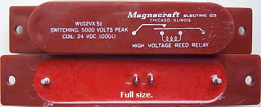
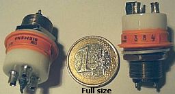
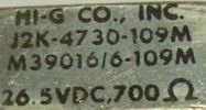
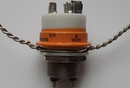
HV Relay, according to the manufacturer the specs are: 10 mA/5 kV or 5 mA/10 kV |
ZL2VB has pointed out that S4 (linear/standby/operate) switch has several spare segments. This section is now being used while in the STBY position with an extra HV reed relay to switch off the high voltage (fig»). It is done for safety reason. The 24-Volt doubling circuit is not connected to ground or frame of the TL-922!
According to the specs of the manufacturer the relay can switch 10 mA/5 kV or 5 mA/10 kV. Because there is no current flowing this system can switch the HV without any problems, even when testing key-down with 1250 watt.
The supply voltage for the step-start relay can be best obtained from the filament transformer. When the amplifier is first switched on, the filament resistance would be low (when cold) and the current would be high. The latter will be limited by a resistance in series with the mains voltage, the relay can't operate if the voltage is to low. When the filament are at the operating temperature, the voltage will rise, the relay will operate and the resistor(s) will be shorted. Everything happens in a fraction of time, which is sufficient to protect filaments and electrolytic caps of the power supply. If for some reason the relay wouldn't operate the resistor would burn out. To prevent this you can put a slow-blow fuse in series with the resistor. Perhaps you can use one of the mains fuse holders (F1, F2), because after all you don't need two!
QSK SYSTEM
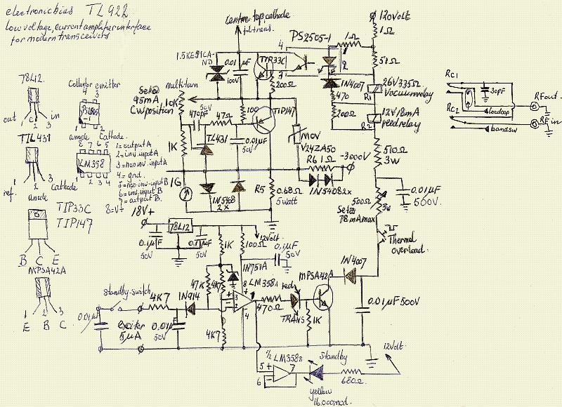
The total of all the mods in one circuit diagram. Up to now everything works perfect.
|
|
|
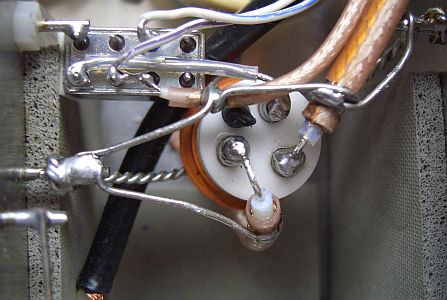
Simple but effective fixed to soldering pins.
The previous owner had used the QSK switching of Richard Measures AG6K. That was modified and the "ordinary" 12-Volt small relay with plastic cover was replaced with a faster airtight 26.5 V/700 Ω of HI-G Co. in place of RL2. It was a relay out of military equipment.
The vacuum relay was mounted by means of two twisted copper wires and soldered to 2 existing solder points (see photo's). A simple and effective way and takes very little room. The smaller one of the relays is soldered with one pin to the input circuit, this will give together with the rest of the wiring a strong and self supporting construction. Many owners put it all on a circuit board and that will make the connection longer. With the self-supporting construction they are a lot shorter and the SWR between the transceiver and the amplifier improves on all bands.
At first I wasn't happy with AG6K's circuit, but after replacing RL2 all worked perfect even on CW.
I may replace the two 1.2kΩ resistors in series with the optocoupler with a constant current source or adjust the MosFet that way. In the meantime no other modifications are done.
ZL2VB's MODIFICATIONS
In the lower part of the schematic the ON AIR and STBY lamps are replaced with LEDs and drived without a relay.
POWER INPUT DIN CONNECTOR
The big power cable of this amplifier is troublesome with experimenting and moving of this super heavy equipment and also the manufacturer predetermines its length. After some hesitation to violate a neat looking linear, it was decided to mount a DIN connector. This I do with all my equipment and it was expected that a fair bit of drilling, filing and sawing had to be done.
|
A punching tool set. It would have been an extensive operation with removing some wiring and components. After taking some measurements it seemed that a 30-mm punching tool was the easiest way with very little damage and no removal of components. You can cover up the rest of the hole with a bit of black plastic. |
A 30 mm hole for a male DIN power connector. |
You can get these tools in different sizes, but a set of them is very handy for the DIY. They are also a lot cheaper as one tool. The set was bought last century when it was still affordable. I had a lot of use out of it.
For a stable and safe amplifier use the following minimal changes. Then your amplifier is protected against flashover, random oscillations and supply shortcut (and often more output).
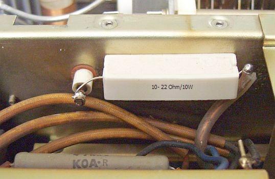
1. FUSE & RESISTOR
If you acquired a 2ndhand TL-922 always starts with the following first modification: a resistor 10-22 ?/10 W and a fast 1 Amp fuse. It prevents a lot of misery as defective tubes, burned grid chokes and much more nasty events.
|
|
|
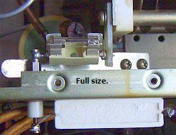
In another TL-922 I did the mounting of resistor and fuse in a different way. If the fuse blows and the lid is lifted the supply voltage is safely short circuit to the chassis. One side of the fuse holder was soldered to the supply feed-through. The other side to a tubular rivet in a slit of non-cladded PCB that was fastens with a screw of the tuning capacitor VC1.

The two extra components have been useful when one of my spare tubes temporarily served as a replacement. The tube worked smoothly with a low plate voltage, but when it was increased in the SSB mode there was a flashover and the fuse blows. Without these measures, the tube was damaged by a short circuit and possibly something went wrong in the HV supply. The main fuse at the back is often too large and too slow to prevent this damage.
Note: Each amplifier seems mechanically the same, but that is not electrically. Therefore there is a difference in stability. If you ground the grids directly eventually you have to replace or change the parasite suppressors. Use the hairpin type and if the PA still oscillate, change the size of the suppressors a bit.
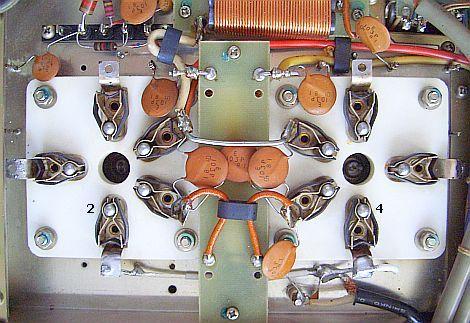
2. GROUND ONE GRID PIN PER TUBE
|
Al components soldered at the pins were removed. |
|
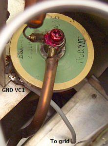
Connect an insulated wire from VC1 ground to («fig) one grid pin. |
A few years after the first modifications I considered that in the tube 3 external grid connections (2,3,4) are bolted to the same point. In nature, is a law of the least energy and therefore electricity follows the shortest path. You can disagree if you like, but I doubt that current flow simultaneously along 3 separate grid connections. So paralleling the external pins is for HF unnecessary. Just by grounding one pin the current is forced to flow via one point and that improves the HF stability of a tube is my opinion. Therefore, all components soldered at the pins were removed and one per tube was grounded.
3. EXTRA GROUND FOR VC1
An insulated wire was connected only from pin 4 of the right tube to ground of the tuning capacitor VC1.
4. REPLACE PARASITIC SUPPRESSIORS
|
|
|
|
The parasite suppressers work well with one resistor and it was tested in this amplifier. The open end of the hairpin was taken little wider for good alignment between tubes and the plate choke.
5. CHECK THE FILAMENTS
The voltage at the tube sockets should be 4.85 - 4.95 V. After the modifications the amplifier worked stable and just as good as my own linear.
BTW: I used the TL922's to test some of my ideas and in this article are several good working modifications. In the last PA's that I modified for friends, I mounted one resistor per suppressor and ground only one pin per tube. Use this "update" if you want to modify your TL922A.
COMMENTS
From home and abroad, I still receive many comments on these modifications. It welcomes the increased stability, protection against arcing and many reports that even on some bands they got about 100 W more ouput.
|
|
|
|
On an Italian forum IW1PUR had read about the modifications and after applying he reported the oscillations had stopped and the linear now works perfectly.
NOTE
(1) If you decide to modify the PA, start first with a resistor and fuse in series between HV and plate choke. This is a safety measure to protect the tubes under all circumstances!
(2) If after modification oscillations occurs, an additional feedback resistor usually suppresses them.
(3) I used a TL922 to test some of my ideas, so there are several good working modifications. In the last PA's that I modified for friends, I mounted one resistor per suppressor and ground only one pin per tube.
(4) Here is a quote from an old Kenwood Newsletter...
"After normal tune up of the 922, increase the power output of the transceiver to full output and readjust the PLATE & LOAD for maximum RF power out of the TL-922"
Your Ig will be a little over 200 so make it quick!
During SSB transmission after tuning like this, the Ig meter never deflects beyond 125ma. Average Ig during SSB is what's important. Peak Ig, which your Ig meter will not read, is not important. During tune up I see around 1250W CW @ 750ma Ip @ 225ma Ig.
![]()
|
|