TB3/750 FRINEAR-750
Universal HF Amplifier for Triodes or Tetrodes
(Published as "A REBUILT YAESU FL-1000 LINEAR" in RSGB's RadCom 1998 Dec)
![]() T3 (PNP) can be replaced with a NPN type, but the schematic is less simple.
T3 (PNP) can be replaced with a NPN type, but the schematic is less simple.
|
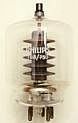
Full size TB3/750. Note: mounting position always vertical |
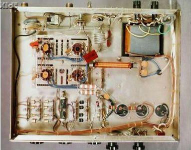
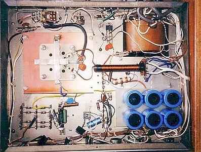
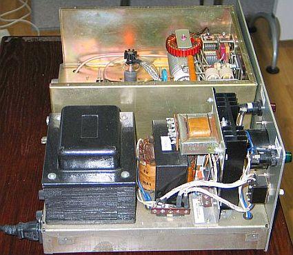
FRINEAR-750 and a modified FL-1000. |
FRINEAR-750
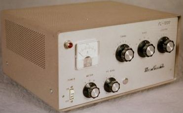
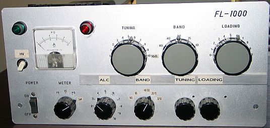
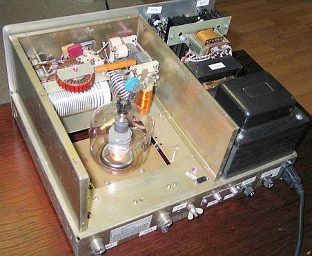
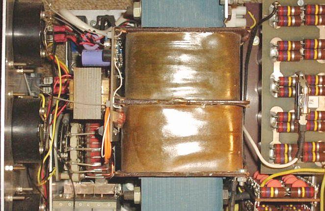
I purchased an old Yaesu FL-1000 (4 × 6KD6) (fig») that had changed bands and countries several times, in the course of which it had undergone various modifications. However the HT transformer, tuning and loading capacitors and the main pi-network tank coil were in good condition. It was purchased with a view to rebuilding with quality components collected during almost 25 years. After rebuilding it produces the same output on 1.8 and 29 MHz. I exchange the PA with a Ten Tec Centaur and then build my FRINEAR 750 with the same design and increased anode voltage.
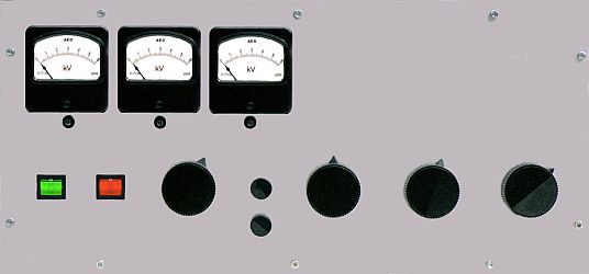
Left: unmod. FL-1000, right mod. with TB3/750 or QB3.5/750 but without tuned input circuit.
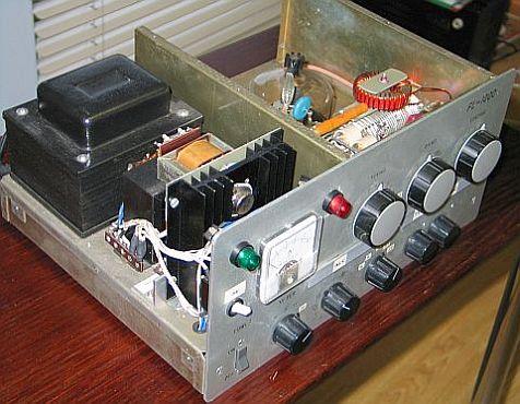
YASU FL-1000 modified with a TB3/750 or QB3.5/750.
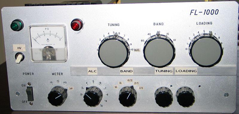
Modified with two extra knobs for tuning and loading of the input circuit.
VARIOUS TYPES OF VALVES
|
|
<TB3/750 3-500Z> |
FRINEAR-750 |
The design of this amplifier has proved most universal, reliable and permits various (fig») type and makes of valves to be used. It was tested with the following valve types: RS686, TB2.5/300, TB3/750, TB4/1250, QB3/200, QB3/300, QB3.5/750, QB4/1100, 5D22, 3-500Z, 3-500ZG, 4-125A, 4-250A, 4-400A, 6155, 8802, GI-7B and GS-35B. See output versus plate voltage and driving power in Table 1 , Table 2 , Table 3, Table 4 .
Joe, I8VYE/0 has homebrewed this design with a QB3.5/750 and with a pulser system in the CW mode he measured the PEP output with a calibrated Bird 4381 power meter (max. hold) and two different set of slugs. Both types gave the same result. On all bands 10–80 m the input SWR was 1.5 or better.
The curve of his test is almost similar to the key down output I achieved with that tube (see the tables). The "paragon" curve reflects his measurements converted to my findings. On 10 meter the PA puts out more watts than my amplifier due to the fact that my 10-meter coil was made with relatively thin 6mm² tinned wire. There are many factors that must be taken into considerations in determining the size of wire that should be used in winding a tank coil. I my design coils of minimum loss were of less importance in practice than the coil size that will fit into available space or that will handle the required power without excessive overheating.

With tetrodes the maximum output is lower, due to the lower maximum HT. It is possible to achieve the UK legal limit with an on-load HT of 1.7 kV and 50 W of drive to a TB3/750. The maximum output obtained with the TB3/750 was about 560 W/1700 V, but this exceeds the maximum rated cathode current.
The key-down current with a 3-500Z was 420 mA and standing current of 70 mA, resulting in a RF output of 430 W.
Tetrodes e.g. QB3.5/750, QB4/1100 and RS676 requires about 85 W of drive for 400 W output. I am not enthusiastic about the 4-125A, 4-250A and 4-400A, with the gain on 10–20 metres falling below the European tetrodes. In general I do not recommend using American tetrodes.
This design is also suitable for Russian triodes such as GI-7B («fig), GS-31B and GS-35B(GS-7B)
TB3/750 TRIODE
|
The first design.
The second design. |
The lower diagram was for the rebuilt amplifier using a single TB3/750 triode. Some features may be of interest and encourage other experimenters tackling a high-power linear:
One switch to cope with many types of valves.
Idle current should be about 60 mA. Zenerdiode: Anode 1700 V = 2 × 27 V, 2500 V = 2 × 47 V.
All-bands pi-input network.
|
|
|
If you want to add or optimise a fixed input circuits for each band, it is best to use the C-values giving in the table. Starting with the fixed input value, experiment with Lx and Cx to get the lowest SWR. Replacing Cx with a piece of coax cable terminated with a variable capacitor (Ct) makes for and easy to reach adjustment. Be aware that the cable capacitance has to be added to the found optimum value of the trimmer at the end of the cable. This then becomes the value of the fixed capacitor, so Cx = Ct + Ccable. Finally eventually adjust C for improved SWR.
|
|
|
A tuning/SWR indicator.
Simple and low-cost panel meter circuit.
Sequential changeover system.

T3 (PNP) replaced with a NPN type.
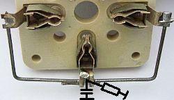
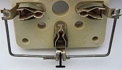
Adequate extra grounding of the stator plates to an "one" ground point at the grid.
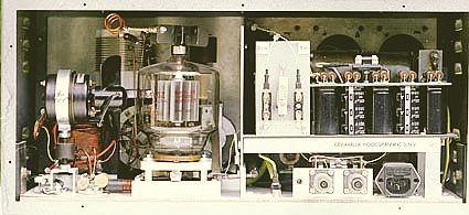
In fact the tube is placed in a screened box that detours the current from the stator plates to the tube socket. An extra short thick wire shortens the path, improves overall stability and efficiency on the higher frequencies.
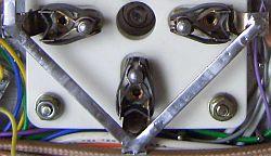
|
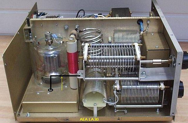
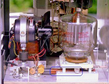
Improved efficiency of an AEA LA30 amplifier on the 10 m band with adequate mass wire applied to the tuning cap's stator plates. |
At the highest band, the tuning-C cannot be made small enough because of the high capacity of the anode circuit. It consists of the combined anode capacities of all valves, about 10–15 pF for the tuning capacitor's minimum and about 4–8 pF for stray capacity. At about 5 pF anode to grid capacity for one valve, our total minimum tuning capacity raises the loaded Q at 10 m and perhaps even at 15 m. This results in lower efficiency through higher circulating current losses and a lowered output at the antenna terminal. However, the situation is not that bad. We may consider the anode- and stray capacity as the C of a separate L-network in which the lead from anode clip to tuning-C acts as an inductance. We then see a combined L- and PI-network. Assuming that the anode lead is about 12 cm long (about 0.06 μH –> reactance = 12 Ω at 30 MHz), we may obtain (by the necessary parallel-to-series conversion) an equivalent driving-point impedance which may be about 30 % lower, and an associated shunt reactance which is also much lower. The net result of this analysis can be an explanation for the still reasonable circuit efficiency in the 10 m and 15 m bands. However the plate tank capacitor should be mounted as close to the tube as temperature considerations will permit, to make possible the shortest capacitive patch from plate to grid. Especially at the higher frequencies where minimum circuit capacitance becomes important, the capacitor should be mounted with its stator plates well spaced from the chassis, shielding or other metal parts.
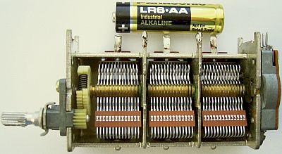
At 750 Watts and a 50 Ohms load, the loading capacitor (± 860 pF) has still only 275 V peak across it, so here the spacing could be even less. However, when detuning with full power, the voltage may rise to several times this value and therefore 500 V should be a safer margin. In practice the old BC-types or newer small types with 3 or 4 sections (fig») are very suitable.
|
|
|
Although separate chokes can be used, the filament choke RFC1 has a bifilar winding (double solenoid) 1.8 mm diameter enamelled wire wound on a 10 cm long, 9.5 mm diameter ferrite rod from a broadcast AM radio. While the wire size might appear to be too thin for 14 A filament current, it serves also to provide a resistance to limit switch-on inrush current.
ANODE IMPEDANCE
Normally the anode- or output -impedance is known or can be calculated, or can be taken from a graph. However, hams are in the habit of (mis) using valves in other than normal ways, so available data don't apply. In the past I have built linear amplifiers in a test circuit, following published schematics or design formulae and copying given values of components. After a while however, one will get an itch to experiment with this or that. Quite often in the following years, output was raised after tinkering with the output circuit. With simple means, the results were measured and tabulated, after which I tried to find a matching formula. I found my results to differ from the formulae and tables as found in handbooks of the years '60. In all probability, pure class B or C was then adhered to. Adjustment according to my "found" k = 1.87 in the formula is a good directive for home-brewing linears that are meant for CW and SSB. The anode-impedance of an unknown amplifier's final stage with one or more valves, according to my findings is:
|
Za = Va ÷ (k × Ia), in which: |
|
Za = the (common) anode (or plate-)impedance, (in Ohms), |
|
k = 1.87, |
|
Ia = the (total) anode current at max. power, (in Amperes), |
|
Va = the applied anode voltage, (in Volts). |
One may dispute the value of the last decimal, but please consider that it is the average result of many experiments. It can be argued that the calculations with Za = Va ÷ (1.87 × Ia) formula could be more exact. Just ask yourself what value you should assume for the added capacitance, caused by valve, wiring and stray capacitance's...this uncertainty is much higher than the one caused by a somewhat simpler calculation. As it is, the formulae worked very satisfactory for me.
CALCULATION OF PI FILTER
|
With my formula we find as a suitable anode load (Ra) for anode voltage Va = 1700 V (user defined) and 0.5 A plate current: |
Ra = 1700 ÷ (1.87 × 0.5) = 1818 Ω. |
|
The anode-circuit must transfer energy and the circulating current amplification factor Q helps to suppress the generated higher harmonics. A loaded-circuit Q of 10–12 will meet most requirements regarding efficiency, suppression of harmonics and practical values of C and L. If we assume for the 80 m band |
Q = 10, |
|
then the loaded circuit-impedance becomes |
Za = Ra ÷ Q = 1818 ÷ 10 = 182 Ω. |
|
The tuning-C (=Ct) is mostly responsible for circuit-resonance, which occurs at the frequency for which |
Zct = 182 Ω. |
|
We recalculate to obtain pF's: |
Ct = 106 ÷ 2πfZct, in resp. pF, MHz and Ω. |
|
For 3.5 MHz this becomes: |
Ct = 106 ÷ (2π Χ 3.5 Χ 182) = 250 pF. |
|
This includes anode capacitance, wiring capacitance and stray capacitance! The circuit transforms the anode-impedance |
1818 Ω down to 50 Ω, |
|
giving an impedance ratio of |
1818 ÷ 50 = 36.36 |
|
and a capacitance ratio of |
√36.36 = 6.03. |
|
The second C, normally called loading-C (=CL), has a value of |
250 (pF) × 6.03 = 1507 pF. |
|
Now we calculate the value of L: Across the coil L is the series combination of |
Ra + Rload = 1818 + 50 = 1868 ?. |
|
The loaded coil with a Q of 5 will, at resonance, see a resistance of: |
Rs = 1868 ÷ 10 = 186.8 Ω. |
|
Calculating for inductance gives: |
L = Rs ÷ 2πf = 186.8 × (2π × 3.5) = 8.49µH. |
SP6AZM has created a program providing quick connection to the desired information: Click PIF_Eng.exe to open the program.
ANODE, PLATE CHOKE
About plate chokes, varying stories circulate. The choke is shunted across the tank circuit, and is subject to the full tank RF voltage. If the choke does not present sufficiently high impedance, enough power will be absorbed by the windings to cause it to burn out. To avoid this, the choke must have a sufficiently high reactance to be effective at lowest frequency, and yet have no series resonance's near the higher-frequency bands. However, least problems arise with one-layer chokes. Because of the dissipation and closeness of the power valves, a heat-resistant coil former is a must: the heat and intense IR-radiation of a power valve at maximum dissipation can make phenol board at 2 cm distance burst out in flames!
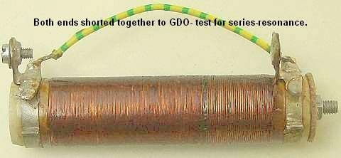
A sturdy ceramic wire-wound resistor, with its resistance wire removed, will make a good former. A diameter of about 2 cm and a length of 10 cm is satisfactory. Closely wind the former with one layer of 25–28 SWG enamelled wires over a length of 5–10 cm. In most cases its inductance is sufficient, even at a lowest frequency of 1.8 MHz. To test for series-resonance, short both ends together («fig) and (with a GDO) checks for resonance's in the amateur bands. If there are none, you are lucky.
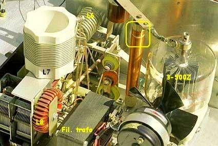
If there are, try to shift them by removing or adding some turns. Another solution (fig») is to remove 1 cm of the windings and start again, leaving a gap of 0.5 cm between windings; then check again. My favourite choke has a diameter of 2–2.2 cm, is closely wound over a length of 5 cm with one layer of 28 SWG enamelled wire, has an inductance of about 180 μH and will serve for all bands. The wire may seem too thin for some currents, but in all my experiments it never burnt through. Since any metal in its field will affect the characteristics of a choke, it should be checked when mounted in the position in that it is used (fig»), or in a temporary set-up simulating the same conditions. The plate end of the choke should not be connected, but the power supply end should be connected directly, or bypassed, to the chassis. The GDO ('dipper') should be coupled as close to the ground end of the choke as possible.
The wirewound resistor (10–50 ?) between +HT and the choke will limit the damage from "flash-over", caused by a momentary short in a valve, to the fuse and (often) the limit-resistor itself. Replacing them is much cheaper than replacing valves.
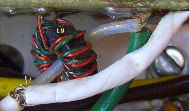
160 m TANK COIL
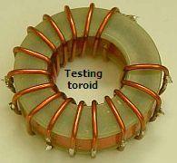
A part (L8) of the 160 m coil (L6 + L7 + L8) is wound on an Amidon T200-2 toroid core. This was done in order to limit the overall dimensions of the amplifier. A toroid, self-shielding because of its low external field, facilitates compact construction. Before winding, several layers of Teflon plumbing tape must be applied to the core, to insulate it from the coil-windings. Another method («fig) of insulation is to cement two flat isolating washers (e.g. made from bare glass fibre board) on each side of the bare core. Apply a small quantity of super glue, possibly only a few drops, around the sides of the core. Work swiftly; the glue hardens quickly. The glue prevents the washers from moving out of alignment while the core is being prepared for winding. For a T200-2 core, the inner diameter should be 28 mm diameter and the outer diameter 55 mm. With this last construction it might be even possible to use bare copper wire for the 28 turns winding of 14–19 SWG enamelled wire.
GRID-PINS
|
|
|
|
In this circuit all grid pins are at earth potential via a 2.2 Ω resistor. At the valve socket, all three grid-pins must be connected together (fig») with short connections of thick wire or ribbon strip (low inductance) and with the resistor, only one pin should be earthen to a common earthing point (chassis, print-board copper side). The grid is negatively biased with respect to the cathode through the forward voltage drop of the string transistors (e.g. power zener diodes), which positively biases the cathodes with respect to earth. In triode circuits, contrary to tetrode or penthode circuits, the bias voltage required for a given anode current greatly depends on the anode voltage: the higher the anode voltage, the higher the required negative grid bias and the higher the value of the two zener diodes.
POWER SUPPLY

Simple soft start circuits to limit switch-on inrush current.
Power supply.
![]()
![]()