HF LOW PASS FILTERS FOR 100 – 2000 W
LPF
A low-pass filter (LPF) is used behind an HF amplifier for suppressing higher harmonics. The problem for a home builder is that often no current or standard values are used for the capacitances in a design. I managed to make such a HF LPF for 1.8 -29.5 MHz with standard capacitors.
With a spectrum analyzer you can determine that this design has a better and steeper curve than many other LPFs («fig LPF30). Pretty soon after 29.7 MHz, the suppression of higher frequencies begins. Optimum operation is possible when the input and output are terminated with 50 Ohm. Three types have been made here for QRP, 200 W and at least 1000 W.
QRP LPF
|
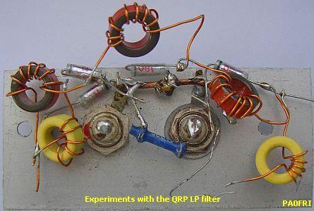
This is a QRP test model. The design is suitable for receiver or measuring purposes. The following types of Amidon ring cores were used: red T50-2 and yellow T50-6. |
|
LPF als noise limiter.
CONSTRUCTION
Because toroids have a negiglible external field, everything can be placed close together so that the filter becomes even more compact than the experimental model on the image. For a QRP transmitter, take wire of 0.6 mm diameter or a thicker type. The thickness is more or less determined by your ability to wrap everything on the ring core and not to break it. A toroid has no half or shorter turns, one wire through it and you have one turn!
ADJUSTMENT
You can use all kinds of measuring equipment for adjustment, but with a transmitter (fig»), SWR meter and inductance-free 50 Ohm resistor it is also possible. Start at 28.5 MHz. By compressing or pulling out the windings you immediately see the effect on the SWR meter. Then repeat with interchange in and outputs. Atn the 15 m band the filter tends to show a slightly higher SWR. So it is a personal matter to find a good compromise between 10 and 15 m.
LOCATION AND ADVENTAGE OF LPF
 The location (fig») of an LP filter is behind a SWR meter. The diodes in such an instrument produce harmonics that must be suppressed. If you notice a strange interference on your TV, this may be caused by unwanted signals from a SWR meter.
This position of the SWR meter has another advantage. Because the input and output of the filter are 50 ohms, the SWR meter will react more pronounced to a slight change of the antenna tuner, so you can better tune to SWR = 1.
200W LP FILTER
 |
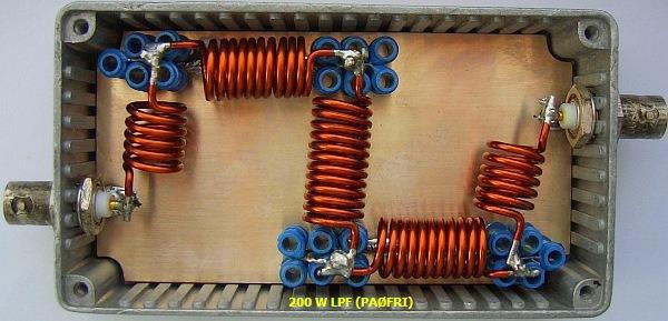 |
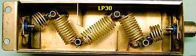
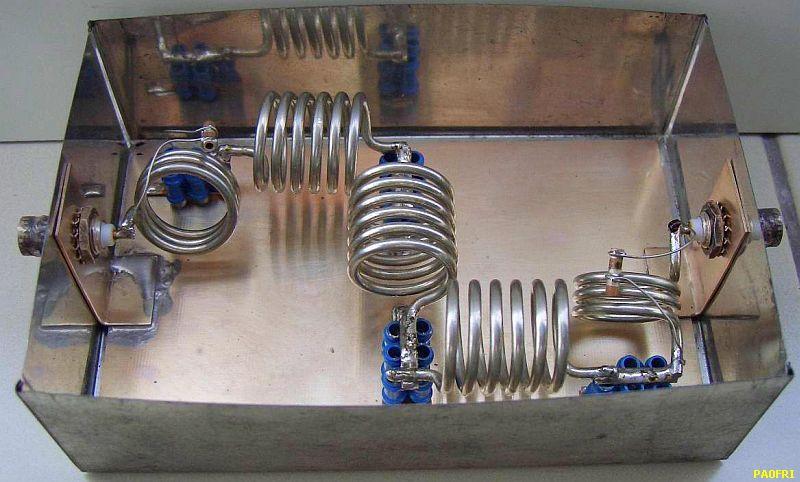
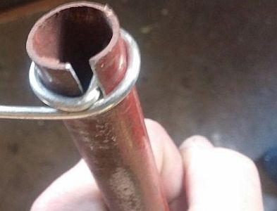
The coils were made of 1.8 mm thick enamelled copper wire. The wire ends are 1 cm and the inside diameter is 1 cm.
Here I wrap the coils on a 9.5 cm drill and then the correct inner diameter automatically emerges. Blue ceramic 30 pF tube capacitors in parallel were used because a considerable number were present.
A ham friend has rebuilt this filter according to the specified coil sizes and it turns out that adjustment was not necessary. You can possibly follow the alignment procedure of the QRP filter.
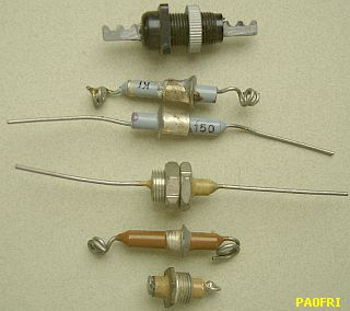
The measurement results were so good that no further effort was made to screen all poles of the filter. If you want to do so, you can advantageously place («fig) standard feed-through capacitors of 150 pF and 180 pF in the dividing screens. With 200 W and such types, I have not encountered any problems. On my spectrum analyzer the graph looks like the pictures below. The center frequency is 50 MHz.
PAØFRI LPF
See the difference between the graph above and the next graph.
HANDBOOK LPF
The slope of the ARRL Handbook LPF is less steep than the PA0FRI LPF.
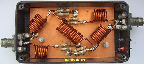
For comparison, a (fig»)" standard "LPF filter was reconstructed according to many older ARRL handbooks.
It is amazing that despite the compact construction the filters maintain a good suppression. Even if dividing screens are installed, the PA0FRI filter is still better without shielding between the filter poles
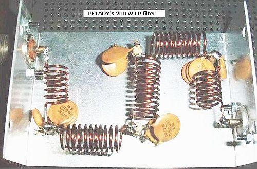
A successful 200W LP filter made by PE1ADY.
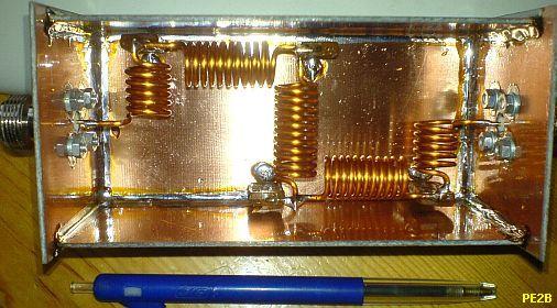
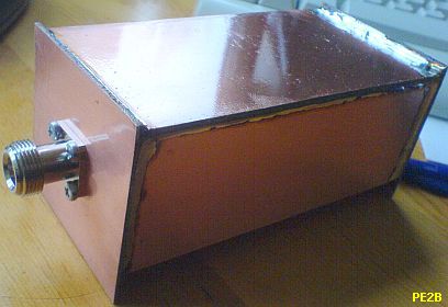
The filter made by PE2B.
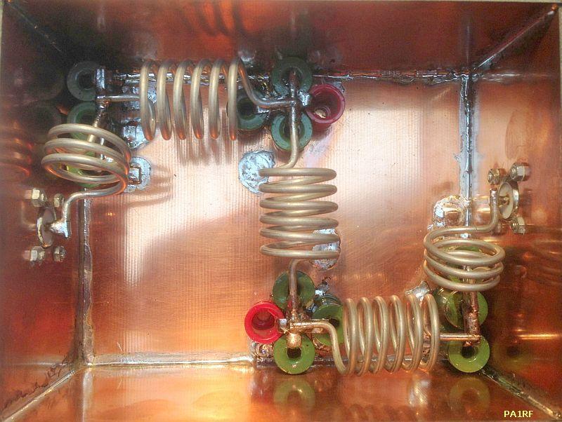
2 kW LP FILTER
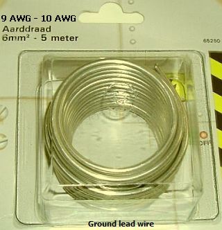
2000 W LP filter made with 6 mm² blank earth wire.
The 22 pF capacitors parallel over the first and last coil induce steeper slope, but reduce the bandwidth.
|
|
|
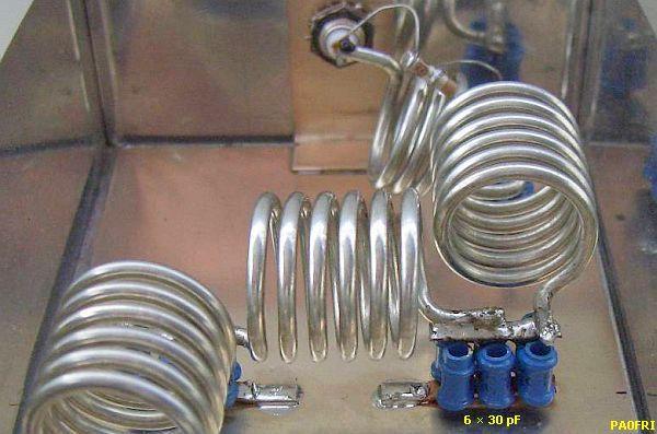
A robust low-pass (fig ») filter can be made of 6 mm² thick tinned blank earth wire that is used for earthing metal objects in the house. The inside diameter of the coils is 2 cm and the wire ends are 1 cm.
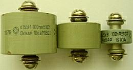
Collecting suitable capacitors for high power is not easy. For 2 kW, the operating voltage must be at least 500 V. It is almost certain that you once operate without load and then it is better to choose a working voltage of a few kV. On flea markets and http://www.elektrodump.nl/en/52-capacitors-high-voltage are still offered Russian toncondensators of 5 and 10 kV.
Because I used less power the required capacitance (fig») is obtained by connecting sufficiently old-fashioned ceramic 30 pF/500V tube types in parallel. However, they have already withstood 1500 W with a correct load without any adverse consequences.
In a lot of commercially LP filters the various coils are shielded from each other. You may match this, but it is not necessary if you perform the assembly according to the images. With this setup, the filter pas band is already better than many purchased models.
Adjustment is done in the same way as with the QRP design.
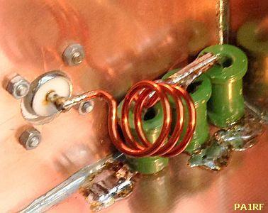
PA1RF
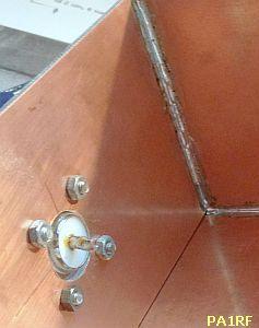
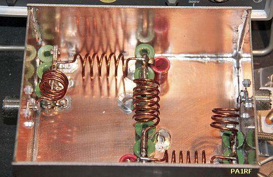
PA1RF has also made the 2 kW type and offered photos of the whole process.
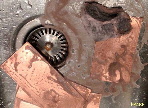
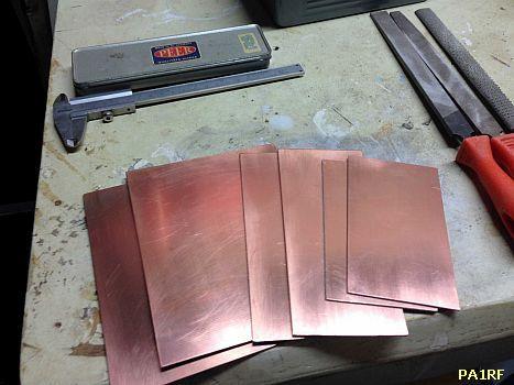
He has omitted the cutting of the various deviding screensside of the box, but you can see how oxidation of the PCBs was removed with sanding pads. I do that too. The various phases of the construction are shown in the following images.
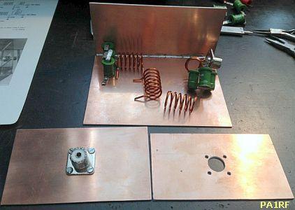
The result is impressive and that is also clearly visible in the graph of a spectrum analyzer.
PA1RF's first structure with "wrong" coils.
The first product was made with thinner wire and the coils had an outside diameter of 2 cm instead of an inner diameter of 2 cm. Some things can be seen at the analyzer's image.
PG8M
PG8M has made a slide show of building: https://davervel.home.xs4all.nl/2KWLPF/index.html
COMMERCIAL LPF's
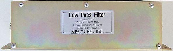
BENCHER YA-1
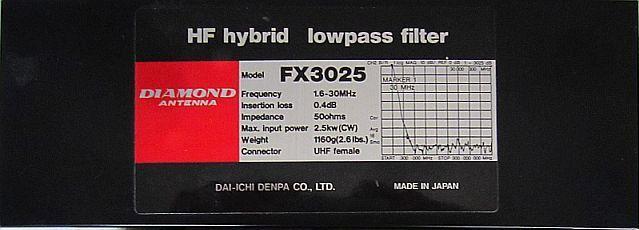
DIAMOND FX3025
![]()
![]()