RF SPEECH CLIPPER
THE CIRCUIT

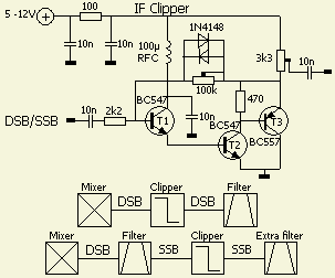
This circuit (fig») was first published in CQ-DL 1974. It is a simple form of operational amplifier with discrete components and was designed as an audio speech clipper. Using suitable components, I was able to use it as a RF speech clipper in several transceivers.
The gain is 100 k? ÷ 2.2 k?= 45 and can be changed by alternative resistor values. If the signal amplitude across the 100 k? resistor exceeds the threshold voltage of the diodes, these conduct, reducing the 100 k? and thereby the gain. As a result, the voltage across the potentiometer does not exceed the threshold voltage of the diodes, approx. 1 V p-p.
The output voltage can be reduced by adjustment of the potentiometer.
If the threshold voltage of the silicon diodes is still too large, they can be replaced by Schottky diodes, e.g. BAT83, BAT85.
The input capacitor must be a low-leakage type not to upset the transistor biasing.
The clipping symmetry can be optimised by changing the value of the 470 ? resistor in the range of 220–860 ?. For me, 470 ? worked so well that I never did it.
RF CLIPPING
It is well known that increasing the effective transmitted speech power with minimum distortion of the audio quality is best done at RF or IF rather than at speech frequencies. To that end, in an SSB transmitter, the clipper can be inserted between the balanced modulator (mixer) and the SSB filter. The latter then removes harmonics and distortion products. If the clipper is inserted after the SSB filter, an extra filter with a bandwidth to approx. 2400Hz is required after the clipper to eliminate those spurious frequencies.
For the usual IF's, up to 10.7 MHz, the complementary transistors BC547 and BC557 are satisfactory.
![]()