(12.15/82.3A types HP, Delta, Hewlett-Packhard and Fujitsu)

INCREASING VOLTAGE SERVER SWITCHED POWER SUPPLY
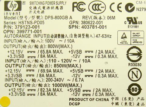
TYPE DPS-800GB A = ATSN-7001044-Y000 K1000 = HSTNS-PD05
(12.15/82.3A types HP, Delta, Hewlett-Packhard and Fujitsu)
![]() 15-Aug-2021
15-Aug-2021
 |
 |
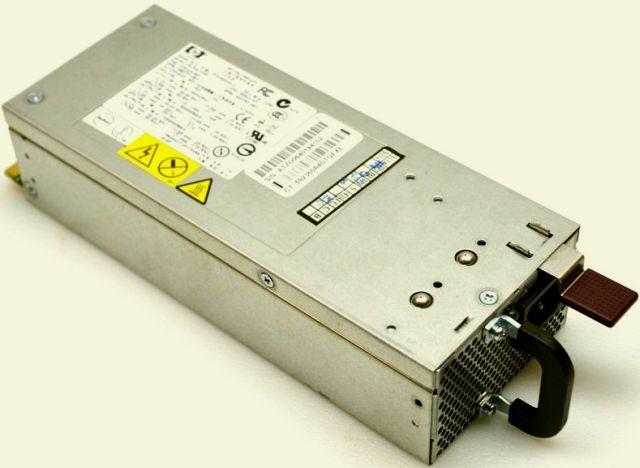
Server switching power supply 200-240 VAC/12.15 VDC/82.3 A. Size metal box (without projecting parts) is 21.5 × 8.5 × 5 cm.
INTRODUCTION
At flea market a server switching 12.15V/ 82A power supply was offered for about €20,-. Because it was pretty small and fairly to the price, I bought it out of curiosity. Searching for a schematic on the Internet was unsuccessful. The supply appears to be a common HP, Delta and Fujitsu model type DPS-800GB A. Also known as type ATSN-7001044-Y000 and type HSTNS-PD05.
INCREASE SUPPLY VOLTAGE
For hams a 13.8 Volt supply voltage is a more usual value than the preset 12.15 Volt. To increase the voltage about eight different circuits can be found on the Internet. Without a schematic it is almost a gamble to design the correct circuit. By measuring resistance and voltage between the tracks I have attempted to find out how it really works. Unfortunately, the puzzle is not solved.
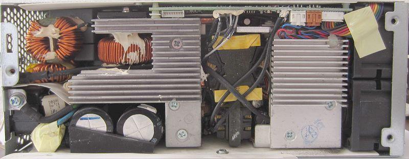
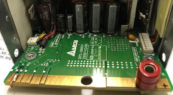
Top view. Main PCB at the bottom.
With an internal potmeter at the main PCB the voltage can be changed, but therefore the very compact device must be completely disassembled. There was no enthusiasm to do it because literally every empty space is used to cram components.
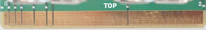
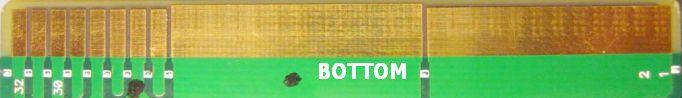
Top and bottom pads.
To boot: connect pads 34 - 31. (Large #Ground and #+12V pads are interconnected on the PCB).
On internet one can not find a schematic diagram. I have had contact with an employee of a company that repairs such PSU's, but the schematic may not be revealed. Probably because the manufacturer wants to avoid the solid PSU will be used for something else. Actually, without a schematic it is almost impossible to design a correct modification to change the voltage. Because pin 32 = remote sense and pin 33 = remote sense return, a satisfactory solution was found by trial and error.
(1) To boot: connect pads 34 and 31.
(2) Install a resistor between pad 32 and ground.
 Start with a 1k5 variable resistor. Reduce the value for an increased voltage. At more than 13.8 Volts the PSU switches off when the load is removed. With connected load power can be turned on and due to the built-in soft start it does not switch off. That is important if one has connected a load such as a car battery.
The maximum current is dependent on the set voltage. With more current the supply swithes off. Under load (Vload) the voltage drops some milivolts. The foregoing is shown in the table.
OTHER VERSIONS
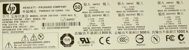
 IØYLI wrote me that his version of the power supply needed 12 kOhm to obtain a higher voltage. His versions are:
MODEL: DPS800GB A REV: 06M
HSTNS-PD05
p/n 379123-001
MODEL: ATSN 7001044-Y000 REV: 06M
serie HSTNS - pro1 BUILD: OC ( o DC)
p/n 380624-001
A German ham had me already reported a similar action for increasing voltage. Apparently there is still a difference in the types of DPS-800GB A, DPS-800GB 1A and DPS-800GB 2A.
This also applies to DPS-800GB 3A, because this type of Markus from Poland could not start with the previous methods until a tip on a Polish site to connect track 31 with 34 and track 26 at earth. The PSU started up nicely with 12.4 Volt and the green LED went on.
SOME TESTS
According to this article one had boosted his supply to 13.8 V, but after an hour load with 9.6 A at 13.65 V the power supply tripped off and becomes pretty hot! Presumably something was wrong with his power supply and for the sake of completeness I did a few tests.
13.7 Volt appears to be the critical voltage of my power supply, because if a considerable load is suddenly connected at a voltage of 13.8 Volt, it switches off while it does not occur at 13.7 Volt.
I loaded the power supply for one hour with 3 parallel connected car lamps of 12 V/45 W. The voltage dropped from 13.7 to 13.53 Volt and nothing unusual happened.
Then loaded with 38 Amp, voltage drops to 12.5 Volts.
Loaded with 95 Amp, voltage drops to 10.5 volts.
Loaded with 96 Amp, supply switched off.
One can not find any schematic on the internet and therefore it is not possible to modify internally without any damage of the supply.
All published start methods or increased voltages are in fact cut and try methods.
 PAØEBC mailed that after a tip on the internet the power supply immediately worked, but with an extra wire from +12 Volt to track 30.
With a load of about 22 Amp the voltage drops to 13.64 Volt, but with 1 Amp it was! At a load of 39 Amp the voltage became 13.65 Volts.
Based on his message I have tried some other possibilities, but with the extra wire worked the best. Without load the power switched off when the voltage was turned to 14.0 Volts. With a 1k5 resistor, the power supply could be set to 13.8 Volts.
With 19.0 Amp for a 100 Watt transceiver the voltage was 13.69 Volt.
With a 47.0 Amp load the voltage was 13.63 Volt.
With 59.0 Amp 13.62 Volt.
No greater load was available.
For the time being these connections appears to be the best.
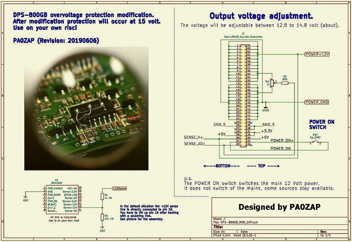
PA0ZAP's MODIFICATION
PA0ZAP has thoroughly researched this type of switching power supply and the result is shown below. Note that the modifications apply to the type/output he tested.
INTERFERENCE
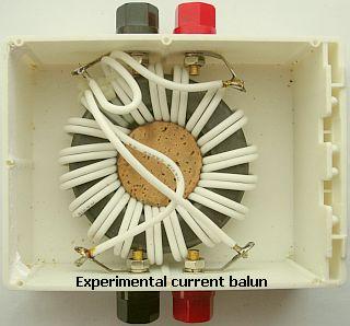
The interference occurs every multiple of 70 to 100 kHz if the sypply is used for a transceiver. The frequency is voltage-dependent. Noise level at 160 m is strongest and it decrease at higher bands. At 20 meters, it is not so annoying.
It is not excluded that noise can be suppressed or eliminated with filters in feeding cables. For a test I temporarily used a current balun from an antenna system as suppression filter. The interference continued but was decreased so that receiving was not bothersome. Presumably a better suited filter will solve the problem.
DIY
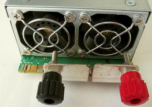
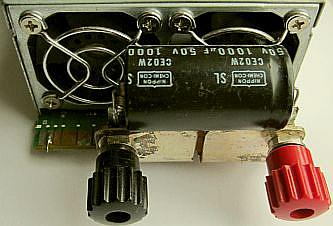
Positive and negative terminals installed.
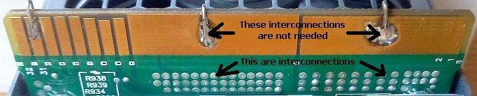
PCB's tracks of top and bottom, of respective #ground and #+12V are connected internally. Further the PCB has a conductive intermediate layer of the same polarity.
For practical use terminals are mounted on a brass hook profile wich is soldered to the top of the PCB. For better conduction the tracks on the bottom are soldered with copper foil to the bracket.
DRILLING HOLES
Be careful when drilling holes in the PCB. Someone from Switserland did that for fitting sockets. Then there was no ouput, a strange sound occurs, the fan did not work and the LED did not light. It turned out that the print consisted of several layers and that by the drilling apparently print tracks were interrupted or shorted.
COOLING
The two small fans make little noise and still works so well that during a ten minute load of 85 Amp the housing was only lukewarm. The power supply is a powerhouse in a very small size!
DEACTIVATE SENSOR PIN
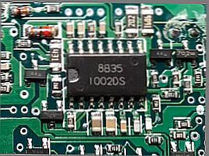
For me it works well with 13.8 V by installing an extra elco (fig») parallel at the output, but the overvoltage protection can sometimes trip. You can lift the sense pin of the voltage detector 1002DS or cut the track. It seems that the output voltage can be increased to more than 16 Volts. I have not (yet) tested deactivating pen 9 because it is a hassle to get to that IC!
See for example: DPS-800GB Full Hack Including OVP Hack
![]()
