ZS6BKW ANTENNA
![]() 22-may-2022
22-may-2022
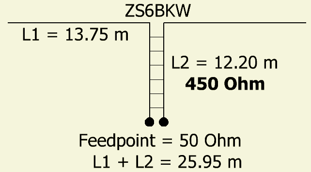
Various sizes of a ZS6BKW antenna can be found on the Internet, so that the original design of ZS6BKW is often overlooked.
G5RV
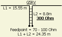
ZS6BKW 's design was based on the original G5RV antenna, a 2 × 15.55 m dipole fed with a 8.8 m long 300 Ohm ribbon line. The system has an impedance of 70 - 100 Ohm and for connection to a transmitter a ladderline of 70 - 100 Ohm was used. At the time, not many amateur transmitters had an output of 50 ohms.
G5RV IMPROVED
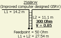
With the help of software, a G5RV has been re-modeled for a more favorable SWR on several bands. In order not too much violate the original design, a 300 Ohm ribbon line with a velocity factor of V = 0.85 was used. The result is a 2 × 14.2 m dipole with a 11.1 m long 300 Ohm ladder line. In contrast to G5RV's design, the improved version has a 50 Ohm feedpoint!
ZS6BKW

Because the 300 Ohm line is no longer easy to obtain, the program was used with a 450 Ohm type. The final ZS6BKW antenna is a 2 × 13.75 m dipole fed with a 12.2 m long 450 Ohm ribbon line. The feeding point here is also 50 Ohm.
The improved SWR is retained with an antenna as inverted "V" configuration, only the resonance decreases. Not so strange because the increased capacitance of the ends to earth makes the antenna electrically longer.
ZS6BKW VERSIONS
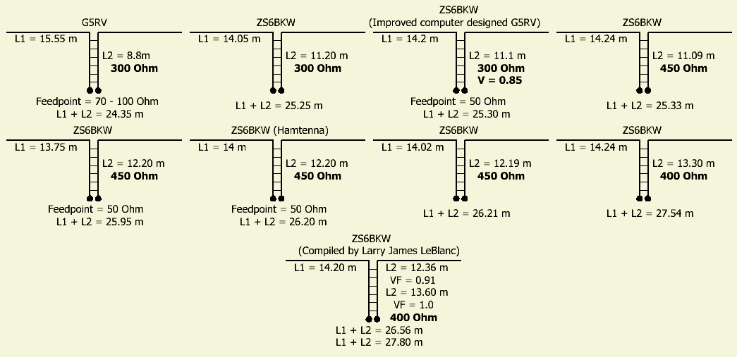
Other ZS6BKW's versions.
The aforementioned better SWR is very dependent on antenna height, subsurface, environment and applied "hardware". Other versions of a ZS6BKW probably were figured out because the designers or publicists aimed for an lower SWR at their location.
COAX FEEDER
The feed point of a ZS6BKW is 50 Ohm, but count of 'about' 50 Ohm, because a random length of coaxial cable works as an impedance transformer. As a result, it is possible that the transmitter is loaded with an impedance lower or higher than 50 Ohm, confirmed by the SWR meter. Suppliers of ZS6BKW or G5RV advise or mention explicitly that their product only works well with a certain length of coaxial cable.
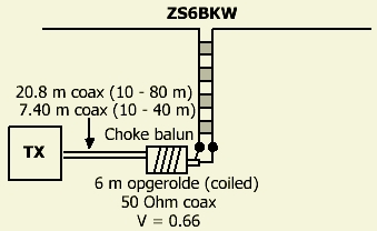 Use preferably a ½ wave (½λ) coaxial cable at the lowest frequency. That works for many bands as 1 ÷ 1 transformer, so that the transmitter at the beginning of the cable has the same impedance of the antenna system.
I prefer to use a multiple of 6.70 m, 50 Ohm/V 0.66 coaxial cable. For 10 - 40 m it is 2 × 6.70 m = 13.4 m and for 10 - 80 m it is 4 × 6.70 m = 26.80 m.
It is also better to install a balun (choke balun) between the asymmetrical coaxial cable and the symmetrical 450 Ohm ladder line. For example by winding close to the feedpoint an about 6 m coaxial cable on a pipe of 7 - 12 cm in diameter. An other line insulator can be made by applying as many windings as possible of RG58 types coax on a FT240-43 toroid.
SIZE OR LENGHT
Always keep in mind that specifying size or lenght of an antennae in articles is a guideline. The actual electrical length (or resonance) depends on construction and environment such as: the height above ground, the power line, the thickness of wire or rod, whether or not insulated radiator (velocity factor?), the way of connecting to baluns or insulators. Furthermore, the capacitance of the antenna in relation to "earth" and conductors such as (wet) vegetation, antennae, fencing, balconies, concrete irons, electrical cables or other metal structures on or in the ground. In your situation (surroundend by many houses) you are lucky if an antenna works as an author or manufacturer describes it, but more often you will have to experiment or adjust to get an optimal result for a good working antenna system.
 .
.