DIAMOND X510N MODIFICATION
![]() 30-nov-2018.
30-nov-2018.
|
|
|
|
INTRODUCTION
When visiting a flea market I have been tempted by an offer to purchase a new Diamond X510N 2m/70cm antenna. For the price it was almost impossible to homebrew such a solid antenna. To handle the packaging the antenna is made in three elements.
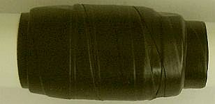
The radiator (fig ») is mounted in a fibreglass radome, tapered like a fishing pole and finished with white lacquer. The coils are made with copper wire and aerial parts of 3 mm brass rods. To avoid rattling the radiator was (coaxial) fitted with foam plastic sleeves at approximately equal distances. The radiator is easily removed from the fibreglass poles and the sizes of the radiator elements are mentioned in the headline of this article. The total length of the antenna is 5.20 m. The antenna can bend in high winds and that disturbs the vertical polarization. So the transmitting and receiving signal strength is subject to instantaneous differences. In the Netherlands the X510X therefore is called a "calm weather" antenna. On the Internet enough positive information is published about this model, so I will confine only some details.
THE NAKED TRUTH


The Bottom of lower element until the 8 turns coil.
MATCHING
|
|
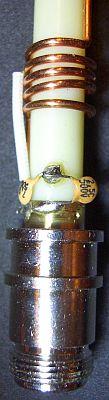
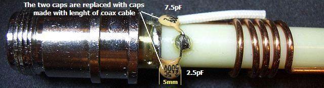
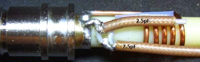
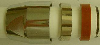
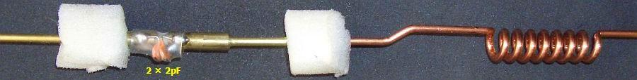
The base of the antenna is loaded with a coil of 4.5 turns and 1 cm inner diameter. The input is matched to 50 Ohm with a 7.5 pF - 2.5 pF capacitive voltage divider connected to the third winding of the coil. According to the specifications the maximum power is specified as 200 W. Not clear if that is true for both FM and SSB/CW. On the Internet one can read that no more than 35 to 50 W is recommended, which is understandable if you see the small 500 V/5 mm diameter ceramic capacitors.
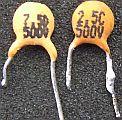
Out of curiosity, the antenna was disassembled so it was only a small step to replace the capacitors. Given the limited space between the coil and the metal tube at the bottom, it was not possible to use transmit or kV capacitors. Therefore, I used 50 Ohm Teflon coaxial cable and cut the cable to the correct frequency using a capacitance meter. If you do not have the meter, a better choice is to buy good quality capacitors.
Another Teflon tube was slid over de quasi capacitors to reduce the stray capacitance. A preliminary test showed the SWR on the two bands was not more than 1.5, which is in line with the original specification.
|
|
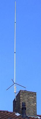
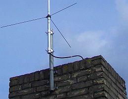
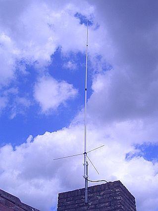
The test was repeated on a 1.70 m pole in the backyard. See the corresponding SWR («fig) in the table. Later the antenna was mounted (fig») on the chimney and the SWR stays identical.
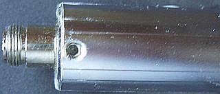
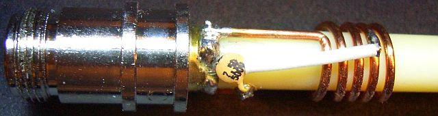
By loosening the socket-head screw («fig), which is secured with an adhesive, you can remove the inside to the left. It is recommended first heat the screw with for example a soldering iron and then unscrew.
OTHER VALUE CAPACITANCE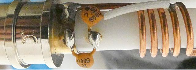
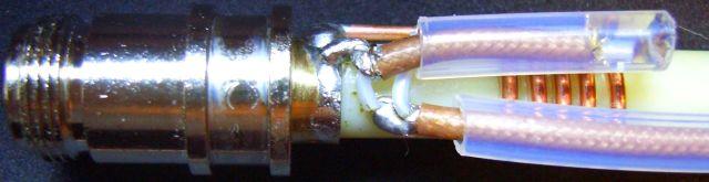
Someone sent me a image of his antenna, where instead of a 2.5 pF capacitor a 1.0 pF type was mounted. The antenna could be a clone, but if it is compared with my antenna, there is no difference seen from the insides are equal.
RESONANCE
Coils and capacitors in series (fig») with the internal radiators primarily determine the resonance of the antenna. I have not replaced the small capacitors, because the energy they have to deal is much less than at the base part of the antenna. To be sure the compression fittings/joint couplers in each element were soldered.
OTHER CAPACITANCES
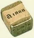 It is often difficult to obtain the same capacitors in small numbers. Think of ATC types (fig ») of for example 500 V. A trader in the Netherlands can supply that type in small numbers, see:
https://dutchrfshop.nl/en/atc-hq-capacitors/301-38-atc-condensatoren.html#/38-atc_waarde-atc_100b_24pf_500_volt
Wire ends will have to be soldered to mount the caps in the antenna.
WETHER PROTECTION
|
|
|
|
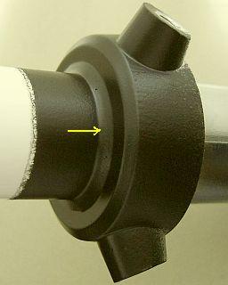
The radome is glued into the Feed Point section, but on the boundary (« see arrow below) of metal and polyester is not covered with paint. My experience with a Cushcraft R5 is that 2 component polyester resin can "evaporate" under the influence of sunlight.
The spot was sprayed with "bumper spray", a black non-metallic spray paint. All my antennas are treated with this product, because after years it proved to be a good protection.
The elements are assembled with joint brackets. For perfect waterproof the joints are covered with self vulcanizing tape and sprayed with silicone spray. The white paint was also protected with the silicone spray.
![]()
![]()