QUAD or LOOP ANTENNA
![]() 19-01-2011
19-01-2011
The characteristic impedance of a loop depends on its shape.
QUAD
The feedpoint of a full wave length (1 × λ) loop or cubical quad (QQ) has an characteristic impedance of approximately 115 Ω. We see that the shape of the loop determines the impedance and the gain (with respect to a reference dipole). A circular antenna is the best and has in a certain direction 1.34 dB gain with respect to a dipole in the same position. Maximum gain can be obtained with a 1.5 λ circumference.
The low gain of a square is explained by considering the antenna as two stacked dipoles («fig) with a to short distance above each other. One dipole feeds the other one by means its high impedance ends, which you can consider as a ladder line with the wires far apart. If one increase the distance (fig») of the two 'dipoles' with a length to width ratio of 3 : 1, the maximum gain is 2.38 dBd. The impedance of the feed point is unknown to me.
|
|
|
To obtain an impedance near 50 Ω («fig) on HF a length-width ratio of about 2.028 : 1 is needed. For best SWR one should experiment with the factor 2.028.
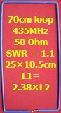
To verify that factor, I have made a couple of 70 cm loops with electricians blue wire. In the center of the 435 MHz band, the SWR = 1.1 at a loop size of 25 × 10.5 cm.
The calculated factor is 25 : 10.5 = 2.38
POLARIZATION
A vertical QQ with a feedpoint on its base has horizontal polarization, the feedpoint on its side change it to vertical. If the antenna is parallel to the surface of the earth, the polarization is horizontal. The antenna becomes more or less omnidirectional and the radiation pattern depends on frequency and antenna height.
IMPEDANCE
The previous information is based on an antenna, which is mounted at great height and under ideal circumstances. The impedance of the antenna close to ground or fitted with directors and reflector drops to a low value of sometimes less then 50 Ω. Usually quads for 20–80 m are relatively close to earth and its feedpoint will be lower (100 Ω) than the theoretical value. The impedance of a half wave (½ λ) loop is 6 - 10 Ω.
ADVANTAGE
A loop antenna has some advantages:
|
Less noise and interference by local sources. |
|
Lower radiation pattern. |
|
Relative low losses due higher impedance ad its feedpoint. |
SIZE
A QQ for one band has a velocity factor of 1.02; its circumference is larger then is usual for antennas.
For example a loop for 3.7 MHz: circumference = 1.02 × (300 ÷ 3.7) = 82.7 m. If the loop is made with insulated (PVC) wire the circumference decreased to about 0.95 × 82.7 = 78.50 m.
If you can not put up a full wave square, a full wave can be simulated with a circumference of 2 × feeder lengths + loop. Differently said: counted from the starting point of the feeder the total length of wire is a full wave.
Although most amateur bands have a harmonious relation, an 80 m loop has not a SWR = 1 on the higher bands.
In the drawing (fig c) you can see that a QQ can be fed with two 50 Ω coax cables in parallel.
HORIZONTAL LOOP
A horizontal loop (fig a) with a circumference of approximately 84 m is a good "all round" antenna for 10–80 m. It has none pronounced DX or local radiation pattern. It is surprisingly how strong the signals on 20 m are with this antenna. A fellow ham lives 10 km away from my location and uses a 160 m horizontal loop. If I transmit with a vertical or W3DZZ antenna on 20 m his reports are one or two S units stronger. Only if my 2 el. Yagi is pointed in the direction of the DX station, we are just as strong and sometimes my reports are better. It must be said that his loop is in open field and I am living in a residential area with a small back yard. I used a 40 m horizontal delta loop with excellent results at my previous address. The loop was about 5 m above the ground and I used a tuner to match the antenna.
MATCHING
The dimension of a loop is less critical if an open line with antenna tuner is used.
Matching of 110–100 Ω to 50 Ω is possible with a balun. By experimenting with my S-Match antenna tuner I found this way («fig) of winding a balun. A big advantage is the galvanic separation of input and output terminals and coupling of the antenna with the coax shield has been nearly eliminated
Eventually the balance was improved by exchanging respective the wires of the input and/or the wires of the output terminals.
In the range of 10-160 m the balun has sufficient inductance.
Here (fig») everything has been clarified once more. Also an (internal) asymmetrical tuner in combination with choke balun is generally possible. Wind (for 10–80 m) approximately 3 m coax on a 7–10 cm diameter tube. If the tuner can't find a match, the feeder cables (2 × 50 Ω) could be to long or to short.
SINGLE BAND QUAD
|
|
Choke balun of mantelstroomfilter. |
A single band quad can be easily loaded with 75 Ω coax cable (fig.a) as line transformer. All that is required is a ¼ λ of line having Z0 equal to √(112.5 × 50) = 75 Ω. The length of line is ¼ × V × λ and that transforms 50 Ω to 112.5 Ω (Zant × 50 = 75², Zant = 5625 ÷ 50 = 112.5 Ω). "V" is the velocity factor.
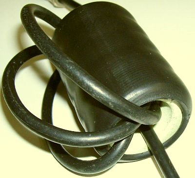
To prevent currents appearing on the outer conductor, wind the cable (photo) a couple of turns through toroids or use a choke balun (fig.b) close to its feedpoint with turns of 3–6 m length of coax on a 8–12 cm diameter pipe.
I use a (grid)dipmeter to determine a piece of ¼ λ cable. I cut a length of slightly more than ½ × V × λ and solder a small loop to one end. Then I short-circuit with a pin through the screen the other end and measure the resonance. After a couple of "punctures" one finds the correct half wavelength and half of it is the correct size.
Matching with a ¼ wave or ½ wave coaxial cable is pretty well known, but it also can be done with an existing 1961 system: two one-twelfth-wavelength transmission lines
80 OR 160 m ANTENNA
![]()
|
|