2m QUAD TURNSTILE ANTENNA
![]() 04-feb-2021
04-feb-2021
2 m Wide band quad turnstile antenna)
INTRODUCTION
Nowadays with all those 2m repeaters and many used vertical radiators, this omni directional horizontally polarized antenna probably will not be interesting anymore. I adopted the principle of a turnstile dipole antenna (fig »).
I assembled the antenna in 1972 or 1973 and even mounted it with sturdy suction cups on my car roof for quite some time in order to have a mobile connection with the horizontally polarized directional antennas used by 2 m amateurs. It will be clear that I had a lot of interest from cardrivers on the way and was suspected of being a member of some mysterious civil service.
The antenna is so wide-band that with a mounting of 10 cm above the roof, the SWR remained almost the same. With a modern spectrum analyzer the broadband behavior can be very well demonstrated. For measurement antenna and analyzer were connected with a full wave (FW 145 MHz) 50 Ohm coax cable. You can see that the antenna is actually slight oversized, because the resonance is about 139 MHz. In 1972 I did not have any advanced measuring equipment and I was already satisfied with the result.
During one of the first amateur satellite missions (name forgotten), with uplink 2m and downlink 10 m, the antenna was hanging at the ridge in the attic. The flying over satelite could be contacted for a long time. On 10 m one may receive many Western European stations followed by USSR stations. The latter became weaker and then disappeared, while I could still hear myself with CW, until the satellite abruptly stopped due to disappearing over the horizon. Apparently the result was achieved because the antenna has a low angle radiation and/or due to the (circular) polarization. Incidentally, that good performance to my own surprise!
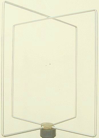
ANTENNA
The loops are made of 10 mm round aluminum tube. No bending pliers was used to gently bend 90° to obtain a square with 53 cm inner sides.
Each loop has an impedance of approximately 100 Ohm. To connect both radiators in phase, a ¼ wave long feeder of 100 Ohm is required.
With 2 × 50 Ohm coaxial cables connected in series, the correct impedance is obtained.
Look after the velocity factor of the coax and the correct («fig) method of interconnections.
Note: By connecting the coax cables in series, the velocity factor becomes larger, if it was 0.66, it would be, for example, V = 0.70. You have to find out or measure for yourself what has become the greater value.
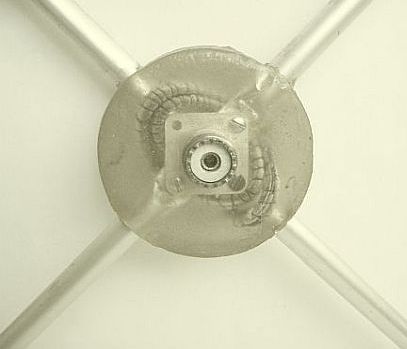
The thin RG174 coax cables used by me are fixed with wire. Then, using (fig») a plastic box as a mold, the rolled-up cables are covered with two component epoxy filler to make everything weatherproof.
![]()
![]()