More research needs to be done to see if my conclusion is correct.
Gamma Match
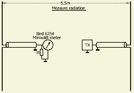
PAØFRI's GAMMA MATCH RULE OF THUMB FOR A DIPOLE ANTENNA
More research needs to be done to see if my conclusion is correct.
Gamma Match
INTRODUCTION
Searching on the Internet for a simple formula to design a gamma match (GM), one is treated with an elaborate mathematical consideration or approach of this adjustment system. In all the articles that I could find on this subject, no practical working example based on all that mathematical stuff was presented.
The consequence is that in all articles published by radio amateurs the GM is the result of experiments to obtain a low SWR.
GAMMA MATCH (GM) SHORTEN ANTENNA
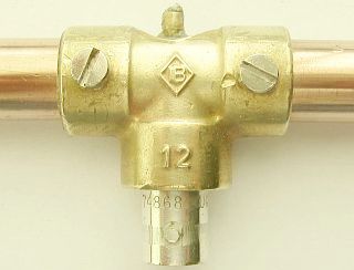
Another aspect is apparently not yet 'discovered', at least there is no publication found by me, is the fact that a GM shortens the relevant part of the antenna! If the GM is regarded as a resistance for convenience, a part of the antenna is loaded and therefore shortened. The GM ensures that the changed impedance of the antenna is matched to the 50 Ohm impedance of the cable. In short, the GM here is a real antenna tuner, because the antenna itself is no longer resonant, but does absorb all energy. In order to obtain a perfect SWR = 1, the GM must be adjusted in combination with the extension of the antenna part.
A GM match sometimes wants to reduces the bandwidth of an antenna, but with this adjustment I have not noticed any change.
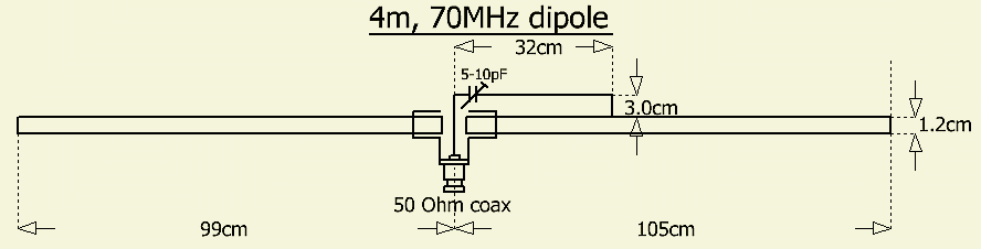
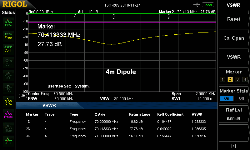
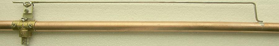
4m, 70MHz Dipole.
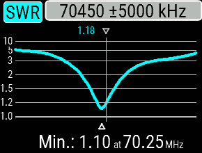 (RigExpert AA-230 Zoom) SWR at antenna. |
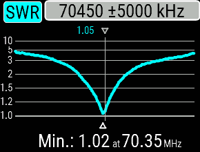
 (RigExoert AA-230 Zoom) SWR with 6m coaxkabel.. |
 (RigExpert AA-230 Zoom) SWR at antenna. |
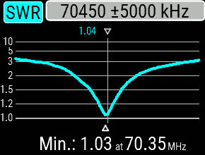 (RigExoert AA-230 Zoom) SWR with 6m coaxkabel. |
It can be seen that for an SWR = 1 the antenna part had to be extended.. To adjust precisely for SWR = 1 with the trimmer was difficult. SWR = 1.01 could even be found, but just a little tap against the trimmer and the dip was off frequency. That is why it remained at SWR = 1.1 measured with a RigExpert AA-230 Zoom analyzer. Due to this small deviation, the coaxial cable already works as an impedance transformer and the resonance after 6 m of cable has shifted slightly.
At a later date, I succeeded with 'Fingerspitzengefuhl' to adjust closer to center of band at SWR = 1.02. That is clearly almost a real 50 Ohm feedpoint, because with a 6 m long coaxial cable the selected frequency did not change.
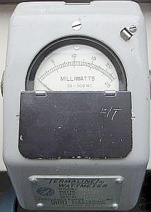
Above are a few examples of my experiments with various antennas.
Please note that my showed antennas are hanging vertically at the ridge in the attic and that the length of your antenna can be different because my surrounding objects can work as a shortening capacitance (= higher velocity factor).
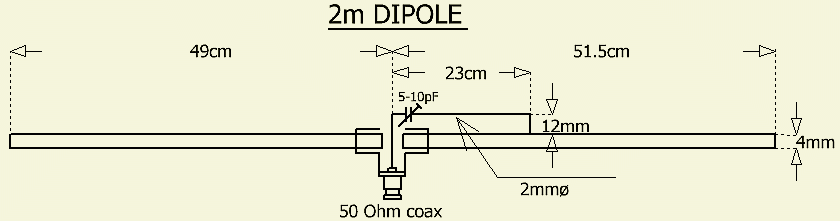
GAMMA MATCH RULE OF THUMB FOR A DIPOLE
Based on my findings, a practical formula or rule of thumb was found to make a GM for a dipole.
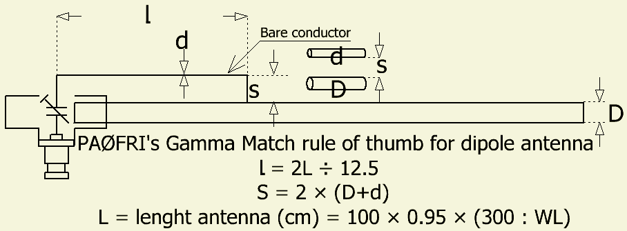
Calculate with the known formula the dimension (L) of a dipole and then assemble GM. Adjust the antenna to minimum SWR with trimmer or other adjustable capacitance. Presumably that will not be exactly on the desired frequency. By gradually extending the relevant half of the antenna and adjusting the trimmer one can reach a SWR = 1, the resonance point being symmetrical with respect to the lower and higher frequencies.
![]()
![]()