COAX BALUN 1 : 4 AND 1 : 1, ASSEMBLE AND USE
(Also balun 1 ÷ 6 en 1 ÷ 9)
![]() 20-nov-2019
20-nov-2019
|
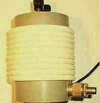
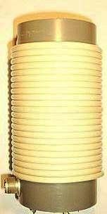
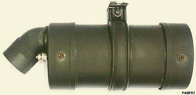
Indoor 1 : 4 balun (33 µH)
Turns ratio. |
|
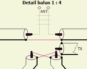
BALUN 1 ÷ 4
An air-wound balun made with coaxial cable can not become saturated because no powder iron or ferrite core is present.
The system consists of two equal lengths of coaxial cable (fig») which are connected in parallel on the one side and in series on the other. If 50 Ω or 75 Ω coaxial cables are used transformation takes place of respectively 25 Ω : 100 Ω and 37.5 Ω : 150 Ω.
 If you want an exact 50 Ω : 100 Ω ratio, a 100 Ω coaxial cable is required. You can use four equal lengths of 50 Ω and then connect two by two in parallel so that two pairs of 100 Ω (fig») are created. Then connect the input of the pairs in parellel and the output in series.
Incidentally, a 1 ÷ 4 transfer ratio will only apply if a real ohmic impedance (not + j or -j) of the correct value is offered. Balancing for a deviant complex impedance remains good, but it is even possible that the transformation is not up but down! Therefore considers this 'balun' as a very good method to transform from a-sysmmetric to symmetrical. This works optimally because the screen is grounded at the output, the center of the load.
Because no core is used, one does not have to worry about whether the core material is suitable for the transmitting power on the relevant amateur band.
In this way, one obtains a balance transformer or balun with an almost perfectly balanced output is my experience. The principle is drawn (figure b) with two coupled coils consisting of 1 × A and 2 × B. The second A coil (braid) does not contribute because it is short-circuited.
In the first drawing, you see that cable A does not have a phase and cable B does have a phase. To sufficiently separate in and out of B, a ¼ wavelength cable would be required. By rolling up a shorter length of cable, an line insulator or choke balun is created for screen of the coax. Since in and output of the short-circuited coil A are in phase, one don't need a coil, it can possibly be mounted separately. In order to keep the whole compact, cable A is also rolled up on the same coil shape. In ELECTRON, VERON's magazine, PAØSE (SK) has published various articles to explain the theory of this balun. Therefore the practical implementation and application will be highlighted here.
BALUNS COMPARED
The balancing of both baluns do not differ much from each other.
 A coax balun and ON7FU balun are compared with my current (fig») antenna. The test was done with 100 Watt and the balun between JC-4 and the RF current system with two meters. With respect to transfer asymmetrical into a good symmetrical system it can be seen that a slight difference exist between both baluns.
The current in the two conductors of the open line is not always the same because, although my dipole is symmetrical in length, electrically it does not have two equal halves on all bands.
You can consider this air balun as a very good transition from asymmetrical to symmetrical and the difference with ON7FU's 1 ÷ 1 balun is small.
This balun supplied by Stockcorner is made from mix 31 ferrite and is according to the affixed sticker suitable for 1200 Watt PEP ouput power.
For about an hour I tested this ON7FU balun with 500 to 600 Watt as follows:
Always change bands and have the JC-4 tuned. That works quickly with interruptions to change the band on the set and activate the tuner. In my opinion, this method can be compared to an intermittent transmission such as an operator who performs a SSB QSO for about an hour.
The plastic housing of the balun became warm and that is probably due to the heating up of the (ring?)core.
BALUN 1 ÷ 1
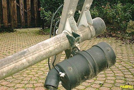
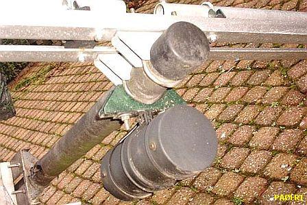
It is also possible to assemble 1 ÷ 1 balun , see the above images.
TO CHOOSE 1 ÷ 4 OR 1 ÷ 1
At that time I could not find in any publication for the second possibility: with a switch (fig») one can choose for ratio 1 ÷ 4 or 1 ÷ 1. If the input of an open line has a low impedance, a 1 ÷ 1 balun is more suitable as better match for an antenna tuner.
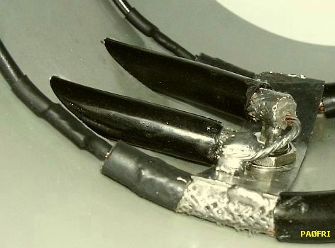
ASSEMBLING
|
|
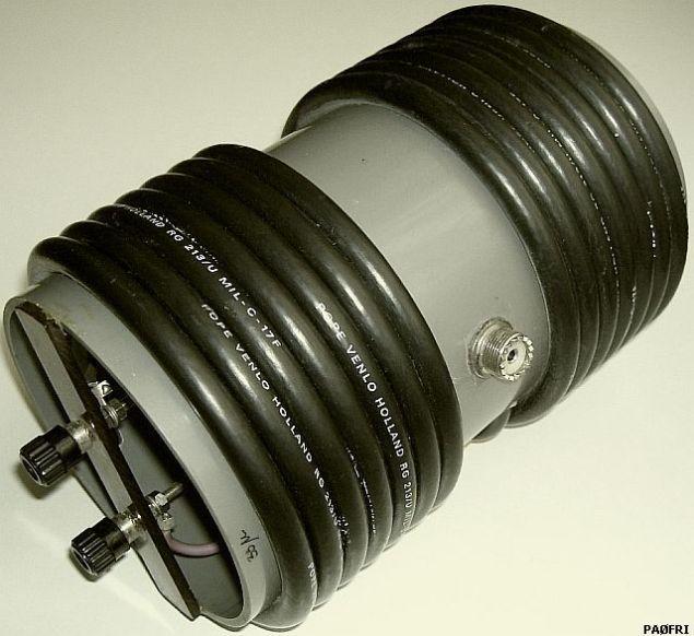
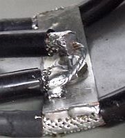
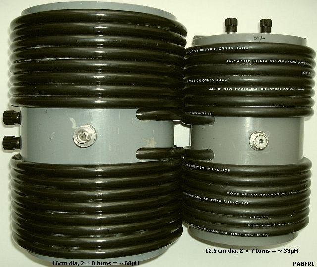
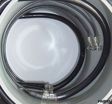
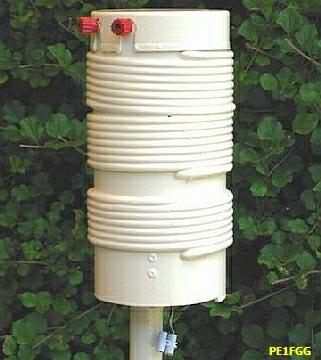
My DIY (for indoors see above) differs from the model published by PAØSE. This was the result of experimenting after reading an article in RadCom's Technical Topics (RSGB). The cables (RG-213/U) are reversed wound onto a 12.5 cm diameter PVC pipe and assembled that inside all ends are as close as possible.
The latter greatly improves symmetry and reduces the added self-inductances of the interconnections. The points of low impedance are close together and high impedance wires are sufficiently separated. With the disadvantage of longer connections, the coils can also be assembled on two separate tubes.
For the range of 10 - 20 m and 10 - 80 m, respectively 2 × 1.5 m and 2 × 3 m are sufficient. If you use 75 Ω cable, then the losses are less than 50 Ω coaxial cable.
The larger model with a 16 cm diameter PVC pipe was made for a friend at a later stage. Its self-inductance is 60 µH. At the ouput of the small model is the self-inductance 33 μH.
SWR
The SWR at the input of such a balun will generally have a low value if the output is terminated with an inductance-free impedance of 200 Ω. The balun has, despite the best possible construction, a relatively high SWR when a 200 Ω resistor with 2.5 cm long connecting wires was attached to the output. The lowest was SWR = 1 at 2.5 MHz and the highest SWR = 5.6 at 15.08 MHz.
|
RG213 |
|||||||||
|
Band |
160 |
80 |
40 |
30 |
20 |
17 |
15 |
12 |
10 |
|
SWR |
1.4 |
1.4 |
3 |
4.3 |
5 |
5.1 |
3.8 |
2.2 |
1.1 |
The noticeable values are the result of a balun that has no impedance ttransformation of 50 Ω ÷ 200 Ω but of 25 Ω ÷ 100 Ω because instead 100 Ω a 50 Ω (RG213) coax cable was used! It will be clear that it is not an ideal balun for a broad-band adjustment of a real 50 Ω to 200 Ω load.
As modem between ATU and feeder is this not an impediment because a important characteristic is used: an almost perfect symmetrical transfer of an asymmetrical signal to a symmetrical load.
Some "experts" have tested this type balun with an analyzer and concluded that the system is not good. Was that test with a practical antenna outside the building?
|
|
|
|
 |
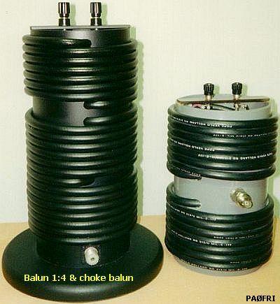
Examples of some homemade baluns. The right can be switched for 1 ÷ 4 or 1 ÷ 1.
ASSEMBLING WITH TOROIDS
The size of the balun can be greatly reduced with suitable toroids or ring cores, for example type 4C6, 4C65 and FT240-43. Try to wind as many windings (PTFE) RG58 coaxial cable on the cores and connect the ends according to the images. The maximum power that this combination can handle depends on the size of toroids and core mix.
If only one core is used, then the second coax cable should be wounded as per illustrated images.
I am not in favor of one core because the magnetization of both halves is never equal resulting in internal conflicts and imbalance.
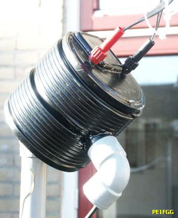
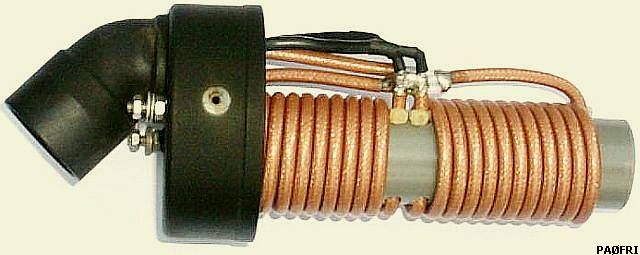
COMBINED BALUN & CHOKE BALUN
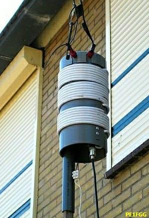
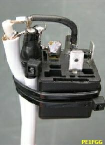
Combined choke balun and 1 ÷ 4 balun.
An even better insulating effect is achieved by adding a choke balun. Use about 3 meters extra coaxial cable for this purpose by winding it below the balun. In fact, that is the last part of the coax cable between ATU and balun. PE1FGG followed that advice and also mounted a relay («fig) in the coil form to be able to choose a 1 ÷ 4 or 1 ÷ 1 ratio.
His findings are:
YAESU FT-897.
Output 30-60 W PSK.
Internal tuner FC-30 (16.5 - 150 Ω, SWR max 1 : 3 )
Antenne G5RV JUNIOR.
With 1 ÷ 4 switched, the internal tuner can be adjusted at 40/30/20/17/12/10 m. An external ATU is only needed at the 15 m band.
USE
Prof. Mike Underhill, G3LHZ devised a system to wide band match a dipole via a coax cable and a 1 ÷ 4 balun at the feedpoint. For this system a simple suitable antenna tuner for HF bands is one coil coil and one capacitor. The SWR in the coaxial cable is lower than a tuner connected via coax to the feedpoint. G3LHZ calls the balun to decrease the SWR in a first step, a pre-match unit (PMU) and the ATU a final match unit (FMU).
My idea was that losses are even less when the balun is not at feedpoint but at the beginning of an open line feeder (fig»). The coax cable should be as short as possible. Extensive tests have shown that the most loss occurs in the connection between tuner and balun. If the balun is installed with a short lenght coax to the asymmetric ATU, then the antenna current is equal to a match with a symmetrical tuner.
IMPEDANCE BALUN
The self-inductance of the coils is an important aspect that often is underexposed is For a good transfer of HF energy, the inductance of the secondary (in Ω) Must be four to five times as large as the adjustable impedance. My balun has a 32 μH self-inductance at the open line side. That is at 3.5 MHz, Z = 2ΠfL = 2 × Π × 3.5 × 32 = 704 Ω (Π = pi).
Because the antenna is not in resonance, an open line acts as a transformer. Suppose an impedance of 600 Ω at the beginning of the feeder line at 80 m. Then («fig) 700 Ω of the balun is in parallel with the impedance of the input of the feeder line. It will be clear that about half of the transmission power is dissipated as heat in the balun. At 40 m is the balun 1400 Ω, at 20 m 2800 Ω etc. The higher the frequency, the better it gets. In this example where the impedance at the beginning of the open line was set at 600 Ω, does an effective transfer at 80 m only take place if the "resistance" of the balun coil parallel at the open line is 600 × 5 = 3000 Ω.
Fortunately, it is in practice not that bad, because the balun is a part of a resonant circuit so that the effective impedance is increased.
LENGHT DIPOLE

My experience with this balun is the length of a half dipole plus the length of the feeder line should be about 27 m (26.5 -27.5 m) for 10 to 80 m. With these lengths the balun's impedance is not too low or too high for this antenna system. With the known G5RV, the ladder line should be about 11.5 m.
At 160 m the lenght should be increased to 54 m (= L1 + L2).
The losses are low because a tuner does not toil. An internal tuner of a modern set can match for SWR = 1.
BALUN 1 ÷ 6, 1 ÷ 9
|
Turns ratio. |
I was asked whether it is possible to make a transfer ratio of for example 1 ÷ 6 or 1 ÷ 9. That is well possible, although I have not yet tested. You must determine the correct tap at the shielding. Only the taps of the left cable in the image are included in the calculation.
FROM 3 BAND TO 5 BAND
Balun 1: 4 to use a 10/15/20 m trap Yagi (FB13 + director FB23) for the WARC bands.
To test the minimum length of an antenna with Underhill's system, experiments were carried out with a 2el Yagi for 10, 15 and 20 m. The antenna is an FB13 with a director of an FB33. Therefore I made a 4 ÷ 1 balun of 2 × 1.5 m 50 Ω PTFE RG-58 coax cable, all wrapped at a 32 mm diameter gray PVC pipe and stored in a standard sewer pipe with lids. This balun tolerated a 15 minutes 1 kW carrier without problems.
As a fixed reference for comparing the configurations of the images, a ham/MM station in the mediterranean area was used. For a few years we had for months amost daily a QSO. My 100 W signal was mostly the strongest signal in the Netherlands.
At the right image only the radiators of the yagi are shown. If the trapdipole was replaced by a dipole (fig b) of the same length and fed with 1 ÷ 4 balun, then I was weaker than with (fig a) the original yagi. Then a half wave (fig c) for 20 m with 1 ÷ 4 balun was mounted and that was as strong as usual. Finally, the original trapdipole was replaced and fed with 1 ÷ 4 balun. No difference was found with the original Yagi, only it was now possible to transmit at 10, 12, 15, 17 and 20 m with the aid of a tuner. As a special feature, 15 m could be worked without a tuner and with about 20 m coaxial cable was the SWR <1.5 on that band.
As an experiment the 1 : 1 balun was replaced by this 4 : 1 balun at my 2el 3band trap Yagi.
As an experiment, this "multiband antenna" was matched with a tuner to 80, 40 and 30 m, some QSO's were made. That occurs even surprisingly well at 30 and 40 m. At 80 meters I got once a S7 report from a station in Amsterdam at a distance of about 150 km.
CONCLUSION
Especially for residents of flats or other locations with restrictions, it is worth to try the Underhill system. Extend the ladder line as long as possible and the coaxial cable as short as possible. Even those who are in possession of an antenna for the pre WARC period, can use their antenna on the WARC bands at low cost and some extra labor.
The coax balun in this article is in my opinion one of the best known transformers with respect to symmetrical feeding.
OTHER ANTENNAS
The balun is useful with G5RV and FD3 and FD4, especially if the set has an internal tuner. If this does not work, extend or shorten the 50 Ω feeder between balun and tuner.
![]()
![]()