EXPERIMENT WITH A 70 MHz/4 m SLIM JIM ANTENNA
MADE WITH WIREMAN SLOTTED LINE
INTRODUCTION
Opinions are divided on Wireman slotted line and that is not without reason. To experiment with it, I got discarded lenghts from a friend because he switched to a better product.
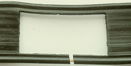
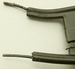
Inspection of the line showed that cracks or gaps had formed in the plastic insulation, as a result of which rainwater had access to the copper-plated solid steel conductors. The copper layer is too thin to protect the steel and therefore the conductor rusts through. Not a good thing!
Because there is space between conductor and insulation, the oxidation (fig») gradually expands further over the conductor.
Based on these findings, my current "chicken ladder" is also equipped with the flexible better product.
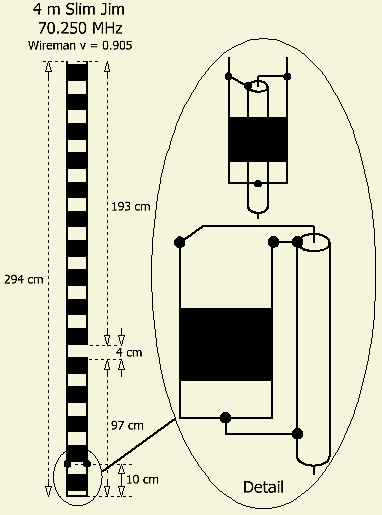
70 MHz/4 m
For local QSO's on 70.450 MHz, a DIY vertical dipole with gamma match is used.
The antenna hangs in the attic on the ridge close to a side window and it is sufficient for a few nearby stations.
One day someone called "cq contest" from Niemandsdorp, which is not so far from my home town of Etten-Leur, but no one heard or worked on that distance. To my surprise, he responded to my call and the report was good. That's why I asked about his used antenna and that turned out to be a Slim Jim (SJ) at about 15 m height and made with Wireman ribbon.
Because the contest would last all day, a provisional SJ antenna was quickly made from the received Wireman and hanged on the same spot as the dipole. It was also possible to work with the contest staiton and the difference with the dipole was minimal.
It is sometimes claimed that an SJ has more gain than a dipole, but that is not correct. An SJ is an end-fed folded dipole and works the same as a dipole. Only it is possible that the folded system is more wideband than the dipole.
An example of MØUKD antenna calculator https://m0ukd.com/calculators/slim-jim-and-j-pole-calculator/ was used to devise the antenna. I had never used his method because almost everything here is always "designed" experimentally. So this was a suitable possibility to test his table for reliability. I have rounded the values.
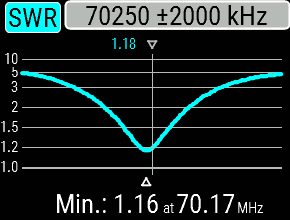
It worked well, but after changing the velocity factor (v) of Wireman's slotted line to v = 0.905, the resonance came to the desired 70.450 MHz. Note: not in the free space, but in the attic.
FEEDPOINT
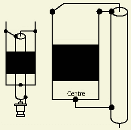
The feeding point of this antenna system is symmetrical and to feed it with coaxial cable one must use a choke balun or line insulator.
With good results I used a different method for home-made sleeve or Sperrtopf antennas.
With this slotted line ¼ wave stub construction, the screen of the coaxial cable is additionally soldered to the center of the short-circuited part of the stub.
With this method, it may be necessary to experiment with the location of the feeding point for the lowest SWR. For me, a rounded calculation according to MØUKD's system turned out to be quite correct.
With a coaxial cable to the shack one floor below and a SWR meter between set and cable, the resonance was slightly shifted to 70.17 MHz with a SWR = 1.16.
FREE SPACE
It has already been mentioned that the experiment was done in the attic. If the antenna is used outdoors, the measurement result may turn out differently. Adjustment is best done if the bottom of the antenna is installed at a height of approximately 3 m.
![]()
![]()