TIPS FOR A T-MATCH ANTENNA TUNER
![]() 24-sep-2022
24-sep-2022
|
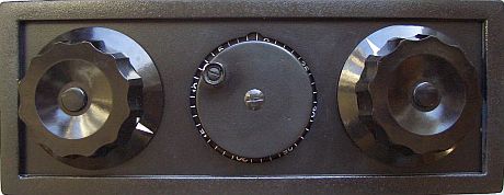
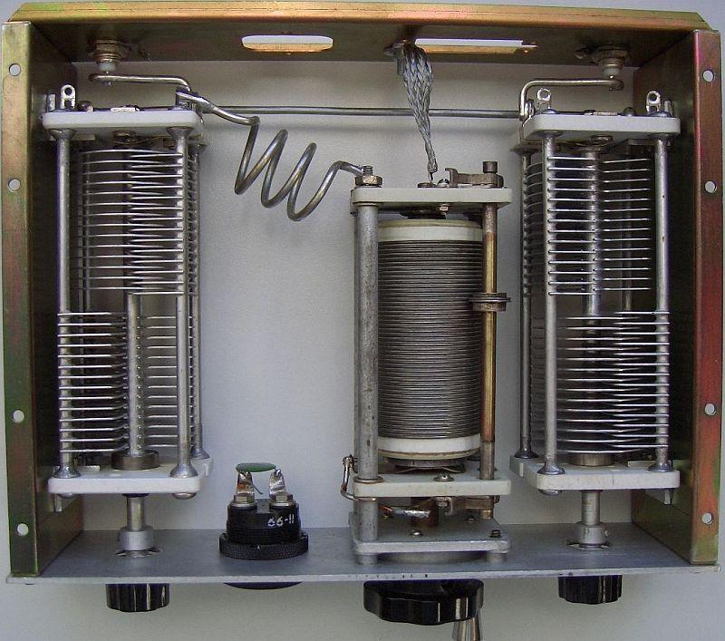
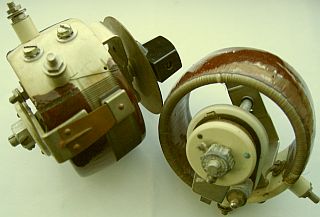
DIY T-match met 1 varialee condensator.
|
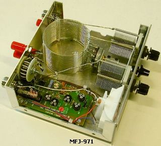
The second variable capacitor (right) was removed and replaced with a with a switch. and fixed capacitor. |
INTRODUCTION
Many hams use a T network (C-L-C Tee, T match, TM), consisting of two variable capacitors and one coil, as an antenna tuner to match an antenna system. A TM is able to tune almost everything from 50 ohms to a higher or lower impedance. Unfortunately, the efficiency is relatively low because the two variable capacitances often do not exceed 220 pF. Better would be twice 470 pF or more, but that makes the tuner much more expensive and bigger.
 A TM is actually developed from a well-known antenna tuner in the sixties: The Ultimate Transmatch (fig »). Soon it was discovered that C3 could be omitted and so a T-match became popular. In England, another type was later recommended: the SPC (series-parallel capacitance) tuner. That design resulted in a greater range and better suppression of harmonics. In my opinion a wrong approach because unwanted products have to be suppressed in the transmitter chain so that a tuner only has to work as an impedance transformer. In addition, the efficiency of an SPC is lower than that of a T-match.
INCREASED EFFICIENCY
|
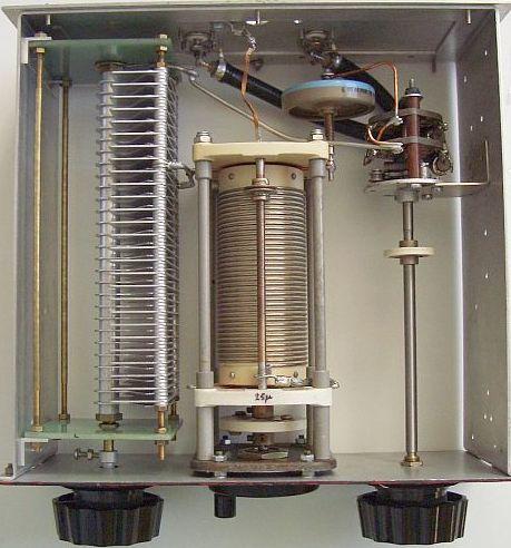
Home made SPC ATU finally modified to a T-match. |
Both a Transmatch and an SPC tuner can advantageously be converted (fig») into a TM. The efficiency is better and the tuning range is increased by the increased capacity C2 + C3. For a fellow ham I converted a Yaesu 10 to 80 m Transmatch into a TM. Then it was even possible to maich, albeit to a limited extent, the 160 m band. The increased range was also noticeable on the other bands. For example, the 40 m band could be tuned with the band switch in the 20 m position.
A T-match is probably the most used matching network among radio amateurs, because it is commercially the cheapest to produce. Pi filters and other tuners need larger and more expensive capacitances to cope the same range.
By resonating this type ATU you probably have noticed that almost always one of the two capacitors has more capacitance than the other. The best efficiency is achieved when one is at maximum and then the second one is tuned for resonance with the rolling inductor.
|
|
|
The efficiency of your T-match can be more improved by increasing the capacitance of the variable capacitors with a fixed switchable capacitor. This capacitor (C3) must be as large as the maximum capacitance of C2 and C3. That is 220 pf in most commercial antenna tuners.
For example, in an MFJ tuner, also a T-match, the variables caps are 208 pF. Incidentally, the 1 ÷ 4 balun at the output of the device can be better replaced by an external coaxial balun.
If one opts for an even higher value of C3, then the two variable capacitors must also have a larger maximum capacitance and that require too much conversion.
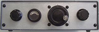
In order to maintain the appearance of a front panel, a switch can be installed at the back of the tuner to select capacitor C3 parallel to C1 or to C2.
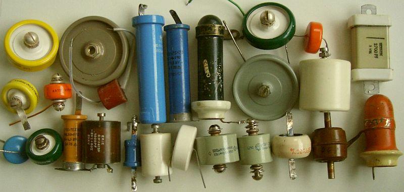
Use as possible transmitting types showed above.
INCREASE RANGE
With a maximum of 220 pF it is often not possible to match the 160 m band. By switching for example 100 pF («fig) the range is increased and it looks like an SPC tuner with the disadvantage of a lower efficiency as mentioned earlier. A better method is to switch in series an extra inductance. In order not to occupy too much space, this can be a coil wound on a T200-2 ring core. With about 28 windings, a self-induction of 10 μH could be obtained.
SIMPLIFIED T-MATCH
|
|
|
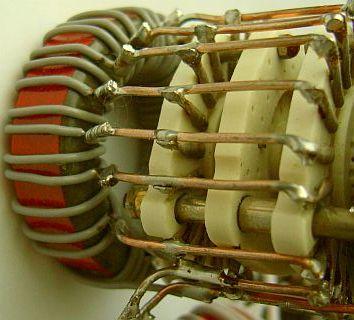
Earlier it was argued that with an optimum match one of the two capacitors is at maximum. In a tuner with a roller inductor this can be exploited by replacing one a variable capacitor with a bipolar switch and a fixed capacitor (left image) of maximum 2 × C. This saves an expensive variable capacitor. For the higher frequencies, the fixed capacitor is almost a short circuit so that the tuner will then look like a (right image) LC tuner. This further promotes the efficiency of the system. On the image you can see that in my DIY T-match a variable capacitor was removed and replaced by a fixed ceramic disc capacitor and switch.
SMALLER COMPONENTS

|
|
|
Small components with a large capacitance are more suitable than people think. The efficiency increases and with, for example, 470 pF or 1000 pF for C1 and C2, less self-induction is required, so the voltage across the coil is lower. This is also a lower voltage across the capacitors so that types with a smaller distance between the plates can also be used. This test model (3 × 330 pF) was even capable of loading 800 W to my antenna with an ladder line via a 1 : 4 coaxial beam without sparking between the plates. With a transmitting power of 100 W, you will be able to use this small tuner with many antenna systems without any problems.
The coil was wound on a T200-2 toroid. The taps, at 1, 2 or 3 windings, were soldered to a ceramic 22 position switch. Because two wavers, the contacts were connected in parallel. I used such a tuner in about 1970. An editor then claimed in Electron that with short-circuited windings on a toroidal core the system would not be able to work (sic!).
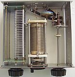
In one of my earlier tuners, the mechanism was removed from a suitable (fig») variable wire wound potentiometer and used to convert a powder iron toroid as variable inductance like a roller coaster.
COUPLING WITH SYMMETRIC FEEDER
When using a symmetrical antenna, the least problems are encountered if an airwound coax 1 : 1 balun is installed directly behind the ATU. See also https://pa0fri.home.xs4all.nl/Ant/Balun/balun.htm
TUNING A T-MATCH
Much is written about the correct tuning of a T network. Everyone does it differently, but rarely nothing is told about the best efficiency. Proceed as follows:
(1) Set both adjustable capacitors in a middle position and search with the coil for resonance through the lowest possible SWR between transmitter and tuner.
(2) If this is not immediately successful, turn the capacitors and possibly the roller inductor step-by-step so that a reasonable SWR is achieved. Usually one of the capacitors has a larger capacitance than the other.
(3) Then turn the largest capacitor to maximum and adjust with the other capacitor and inductor to the lowest possible SWR.
(4) If the last not works, slight decrease the other capacitor.
(5) Repeat step 4 if necessary.
In general, only with a roller inductor match is obtained with one of the capacitors at maximum so that the tuner achieved its optimum efficiency. These settings are mostly not possible when one use a tapped coil. Repeat step 4 to obtain SWR = 1.
![]()