MFJ-989D CONVERSION TO S-MATCH
![]() 06-nov-2018 Update schematics (tnx IW2CFB).
06-nov-2018 Update schematics (tnx IW2CFB).
MFJ-989D conversion to symmetrical S-Match ATU.
INTRODUCTION
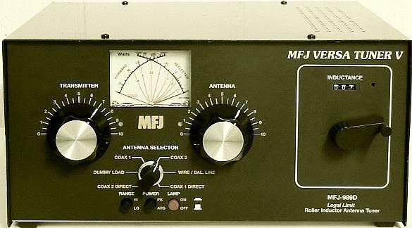
A MFJ-989D Versa Tuner is an A-symmetrical antenna tuner equipped with a T-match (T-network) system. For matching a symmetrical antenna system, a current balun can be switched on. While such a configuration can work well with some ladder line antennas it is not always the best system. A true symmetrical antenna tuner is an appropriate way.
A MFJ-989D with bugs and missing current balun was available to make "something else". A great opportunity to examine whether it was suitable for conversion into a symmetrical system. Because the two variable capacitors were already standard assembled insulated from the base cover, this incomplete device was chosen for conversion to a S-Match tuner.
|
How the idea for a S-Match developed |
Test if a MFJ-989D Versa V tuner is suitable for conversion to a S-Match antenna system tuner. |
An experiment with a provisionally-mounted balun revealed that a modification could be carried out.
SCHEMATIC
The schematic of a MFJ-989D looks like this:
MFJ-989D CONVERSION TO S-MATCH
The part converted to S-Match, looks like this:
VARIABLE CAPACITORS
In a S-Match not only the roller inductor determines the tuning range but also is the minimum and maximum capacitance of a variable capacitor.
In this MFJ-989D each variable capacitor is maximum 2 × 250 pF and minimum 2 × 22.5 pF. With an antenna on a particular band it is possible that maximum capacitance of a capacitor is too little or minimum capacitance is too large to match the system. By changing the wiring of SW2, one can connect the first capacitor (C1) in parallel with the second capacitor (C2) without additional switch.
Assemble two sections of C2 in series so that you have access to a minimum capacitance of 22.5 ÷ 2 = 11.25 pF and a maximum of 500 + (250 ÷ 2) = 625 pF. This is sufficient for matching many antenna systems but sometimes it is a 3-knobs in stead of a 2-knobs tuner. In general C2 is used for 10-30 m and for 40-160 m C1 is connected in parallel.
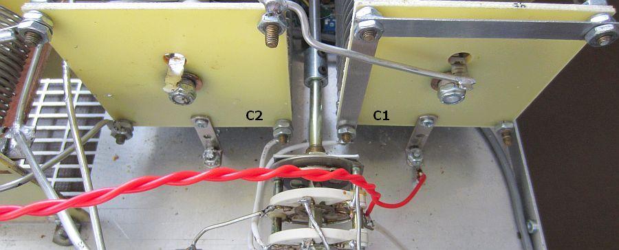
Sections are connected in series C: 11.25 - 125 pF. C1 (= 500 pF) can be connected in parallel onto C2 with the switch.
BALUN
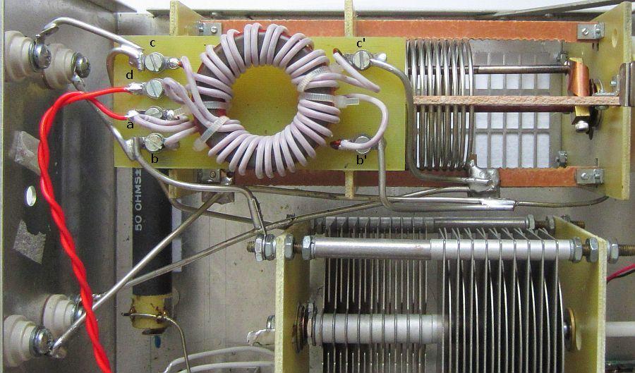
The balun is made with Teflon insulated wire on a red T200-2 toroid (larger type as well). Apply 16 turns (a - d) and two 8 tuns (b - b ', c - c').
Applying windings and connecting to other components of the tuner turns out to be a problem for some people. If something is done incorrect, the toroid core can become hot. The following step by step method will hopefully clarify the construction.
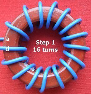
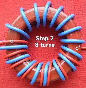
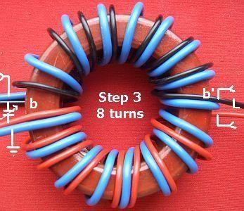
Sequence of windings. Left side connections: blew = input, red & black = capacitor; right side connections: red & black = roller conductor.
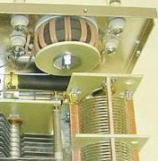
ROLLER INDUCTOR
Manufacturer advertises with superlatives about the roller inductor and the tuner would be suitable for 1500 watts. However the wire gauge of the inductor is too thin for that the power and it is only valid if the antenna system has a very favorable impedance.
My antenna is only 2 × 17.30 m as inverted V. If the MFJ-989D is tuned on 160 m, the roller inductor is getting hot with a 800 Watt carrier during 2 minutes! In my view, 300 W continuous power and 1 kW PEP power is more to the truth for a MFJ-989D! Perhaps is that the reason this tuner is remarkably often offered 2ndhand if MFJ-989D is searched with Google. An American ham was apparently not happy with the roller inductor coil because he replaced it by a type with thicker wire.
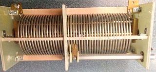
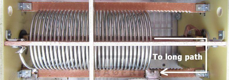
Furthermore the track from slide contact to the end of the roller inductor is to long. This is mainly due to the gap between coil and faceplate. Obvious the inductor (fig») was designed for a different application and manufacturer has removed a large number of turns. The long path is mainly affecting the 10 m band where wiring is the major part of the "coil"! As a result, it is often difficult or impossible to tune the highest amateur bands. If it succeeds efficiency is not the best. Onfortunately the rotary inductor has to be turned anti-clockwise to increase inductance, which is an unusual method. A 180º assembly would have been better in all respects.
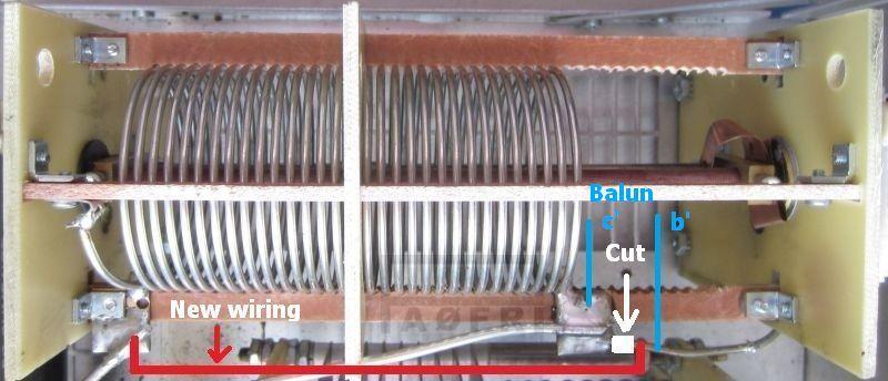
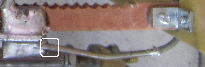
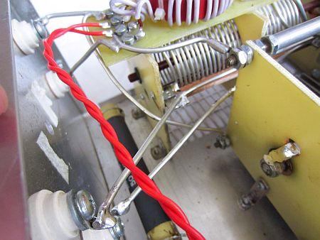
Cut or desolder wire at the arrow and extend (= red wire) to the left side of the inductor.
Wiring changed.
Fortunately, an improvement is possible. Disconnect the wiper wire to the inductor and extend the wire as it is red colored in the image. Now there is more "coil" and less wiring. As additional adventage the roller inductor must be turned clockwise for increased inductance, e.g. counter works correct.
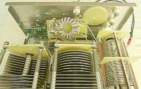
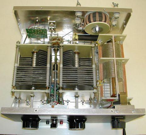
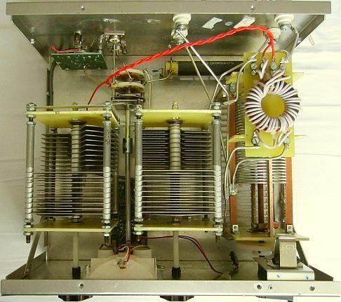
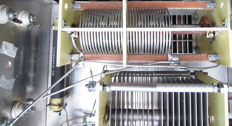
FINAL ASSEMBLY
The final assembly with the shortest possible leads to other components.
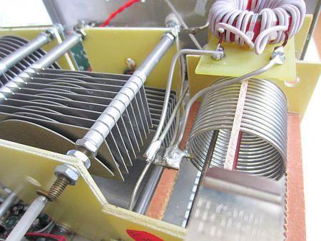
For mounting the balun enough space was above the roller inductor with sufficient distance to the metal top cover. Using a glue gun the copper-free epoxy plate was fastened on the upright plates of the inductor. That in itself is already strong enough, but the 6 mm² mounting wires are extra securing. The foregoing ensures that leads to other components, is kept as short as possible.
The balun is connected as is highlighted in one of above images; see also #b' and #c' below.
TWO BALANCE LINE OUTPUTS
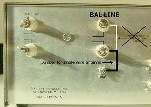
The converted tuner can match coaxial and ladder line antenna systems. For optimum performance the line can be connected in parallel with the roller inductor or across capacitor C2. Both systems have advantages and disadvantages, but parallel at the coil is most in vogue. Try which connection delivers maximum antenna current.
To feed single-wire antennas one of the wire terminal post is connected to the ground terminal post at the back cover.
SWR CIRCUIT
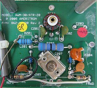
The SWR circuit of some 2ndhand tuners are damaged or defective. MFJ does not sell the SWR PCB, so some DIY has to be done. The former owner of this Versa Tuner is a deceased ham who was only working on some modifications of the tuning section. As I see the PCB he has nothing changed but it appears that the factory did not assemble R201, R205 and C203.
One owner had a burned PCB and parts of toroid T201 were missing so that the number of turns could not be determined. Probably a ferrite toroid of mix 43 such as FT#-43 with 15 bifilar turns can be a good substitute.
Ater an overload germanium diodes D201 and D202 (1N34A) can be damaged, e.g. short-circuited or partially conductive. With some searching on the internet suitable germanium diodes can be found but if not use a Schottky diode (BAT85 for example). A disadventage is that the scale is no longer reliable, only SWR = 1 is real.
![]()