After a few years of experimenting, I think this is the best method to feed a symmetrical antenna system.
The screen of the coaxial cable is "grounded" to the central heating system.
JC-4 AUTOMATIC ANTENNA TUNER
![]() 03-FEB-2020
03-FEB-2020
After a few years of experimenting, I think this is the best method to feed a symmetrical antenna system.
The screen of the coaxial cable is "grounded" to the central heating system.
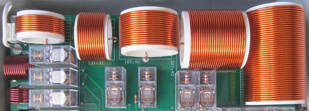
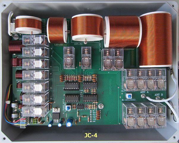
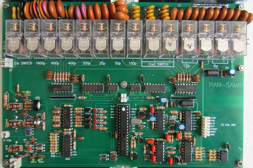
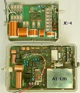
Upper PCB.
Lower PCB.
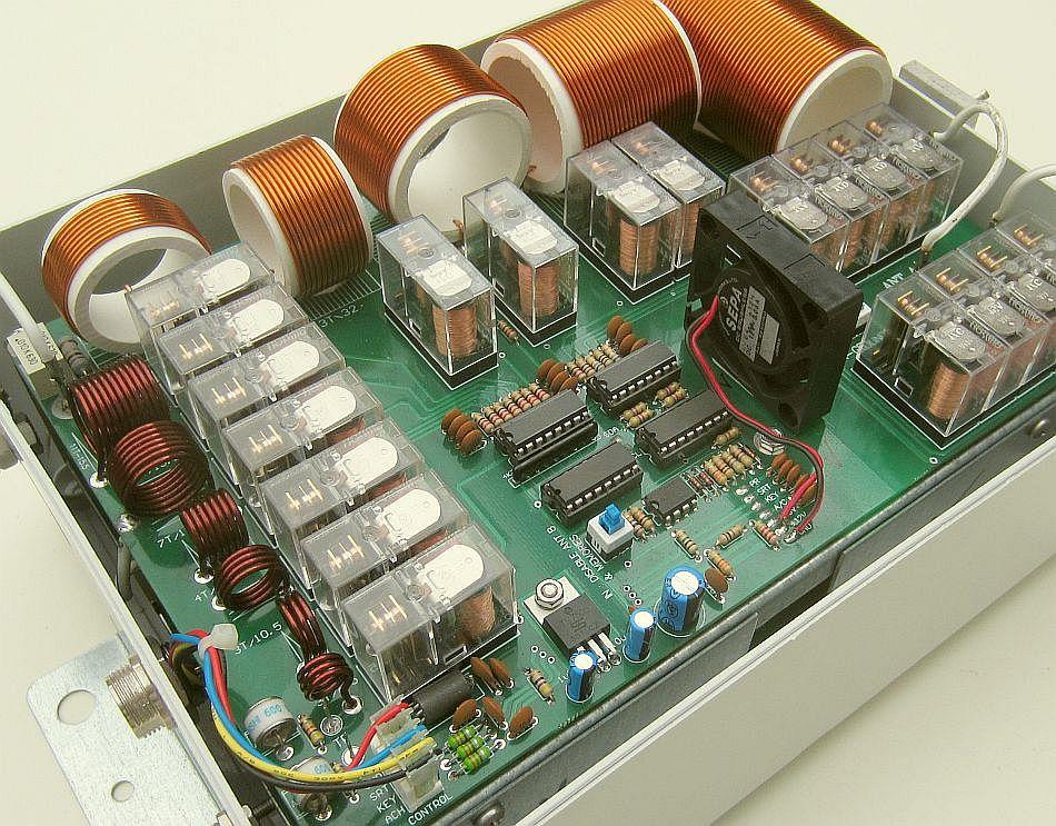
Switched-on relays produced a lot of heat and, in order to cool the coils, a fan with two-sided tape was installed.
SCHEMATICS: JC-4(1) , JC-4(2) , JC-4(3)
INTRODUCTION
 Recently I temporary got a JC-4 automatic antenna tuner for end-fed wire or rod antennas. A welcome opportunity for me to "play" and compare it with my home made ATU and an ICOM AT-120. In terms of price a JC-4 is an attractive alternative to similar but more expensive couplers from other manufacturers. It may be up to a difference of 50% in price:
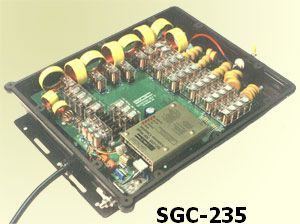
JC-4 1000W/PEP about EUR 500, SGC-235 500W/PEP about er EURO 1000.
JC-4 has 11 coils and SGC-235 8 coils available to obtain resonance.
Most comparative tests were done with my antenna (fig») as shown in the picture on the right. The antenna was symmetrical fed with a current balun or one of the feeder lines was disconnected to use the other as L-antenna.
JC-4
The most important features
1. 1kW PEP (SSB 1.6 - 30 MHz) with a 25 m wire antenna.
2. Remote control with ICOM, ALINCO en KENWOOD transceivers.
3. Tuning steps: inductance 0.08 µH, capacitance input 25 pF and output 6 pF.
4. Automatic selection of CL, LC of Pi-circuit.
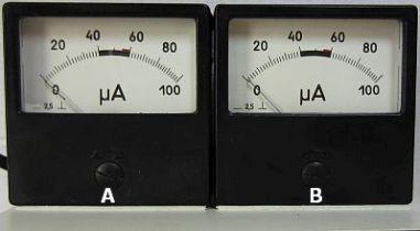
5. Choise of 2 antennas (A en B) both with 50 memories.
6. Switching to A or B without retuning.
7. Not used antenna is grounded.
8. Dipole or open feedline can be connected across antenna outputs A and B.
9. Memory remains when supply switched off.
10. Memory not stored if SWR > 1.3.
11. Protection against static discharge during operation.
12. Both antenna outputs (wing nuts) grounded when powered off.
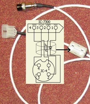
Other than the specified equipment does not apply. For example YAESU devices needs the control box equipped with a 4-pin microphone connector and a 4 core cable. The operation is as follows:
 In the accompanying documentation without schematic is stated that 1kW PEP is allowed (actually with SSB) only at certain lengths of an antenna. For a short time 300 W is possible when transmitting with AM, FM, CW and RTTY. It is not a superfluous advice considering the coils wire size and the fixed-mounted small capacitors.
If one has a G5RV or ZS6BKW, 1 kW PEP is possible when not using 160 m, because the antenna is too short for that big power.
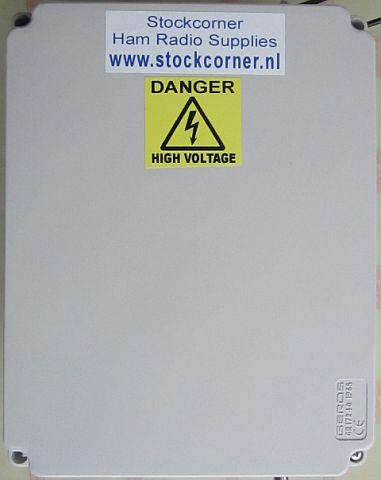
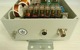
The coax and control connectors (fig») are not watertight is an often comment in reviews, but that is not true, because the relevant feedthrough components are glued. The galvanized fastening strips should be of stainless steel, but maybe it was a method to reduce production costs.
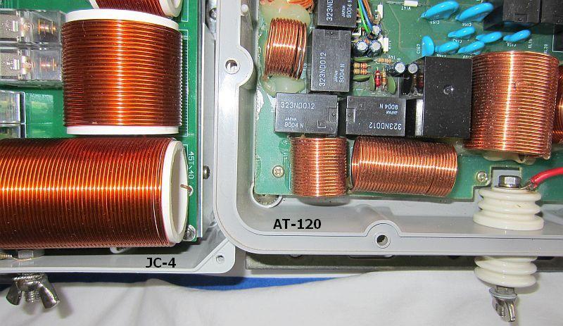
JC-4 wire is thicker than AT-120 wire.
MATCHING RANDOM ANTENNA's
Generally the tuner is able to match random rods and wire antennas, even if no antenna is connected. Not always with SWR = 1 but often with SWR < 2. It will be clear that with a short antenna the bulk of the energy is absorbed in the tuner itself. To protect the device one have to reduce the transmitter power significantly or use recommend length of antenna systems as stated in the documentation. The image («fig) shows that two antennas permanently can be connected to ouputs A and B, so you have a choice of two systems, each with 50 memories. For example very convenient during a contest to select the strongest signal.
When using an end-fed antenna it is important tho connect a counterpoise as drawn in the image. Another possibility is a single insulated wire lying on the ground. The size is about 60% shorter than antenna due to the velocity factor caused by the earth. A counterpoise of 15 - 17 meters is than suited for a "horizontal wire 25 - 28 meters" as recommended in documentation.
RF INTERFERENCE (FEED BACK)
 JC-4 is an asymmetric tuner; (fig») if a dipole is connected directly or with an open line across terminals A and B, all transmit power went into antenna. Only one has more chance of RF interference in own or neighbors equipment. It occurs during one of my tests. Without current balun interference was on 10 m and a digital SWR/Power meter became "confused"; meter remained stable with balun.
 SYMMETRICAL FEED WITH CURRENT BALUN
There were and are still discussions going on about the (best) place of a (choke, current) balun with an asymmetrical tuner. Suppose a giant ferrite bead exists that we can put over a tuner. Then there are three options which are shown in the image: (1) between TX and ATU, (2) over the ATU and (3) between ATU and antenna. In terms of operation it does not matter where the balun is placed. So there is no real difference whether it is before or after the ATU! However, at (1) and (2) the tuner is part of the antenna system with all the attendant consequences such as RF voltage at PCB or cabinet or interference in own equipment. It need not be so bad to happen but it is possible. The best place of a balun is as close as possible to the antenna system, so between the antenna tuner and antenna system. This is my conclusion and on Internet you can find more like-minded comments.
If the balun is getting hot on a particular band it is due to high RF voltage at that point of the supply line.
There are three solutions:
1. Lengthen or shorten the balanced feeder for maximum antenna current at the balun connection.
2. Take a large ferrite toroid or more toroids so that power is distributed.
3. Use a 1 ÷ 4 balun for that band.
SMALLER COAX BALUN
Many experiments have been completed with baluns between tuner and ladderline as you can read further in this article. Currently I am using a smaller coax balun and the currents in the feeder have become almost the same on the higher bands. In terms of balance, an improvement on the larger type of balun. This is most likely due to the reduced mutual capacitance of the windings. Either way, the symmetry on the higher bands has improved considerably.
.jpg)
.jpg)
The larger balun has been replaced by the smaller type on the right.
.gif)
This construction is different from the coax baluns shown in the following paragraphs because there is not enough space in the center of the pipe to perform the necessary work.
The coils are made with RG58 coaxial cable, but PTFE cable is better. It is wound on a PVC pipe of 7.4 cm outside diameter. Two coils of 9 turns have been fitted, but that is not drawn in the image above! The winding direction is the same, but to reduce mutual influence, the cable ends are connected "opposite". When DIY, one must pay close attention to this and that is not shown in the drawing: both cables should be of the same length.
If homebrew is out of the question, then the ON7FU balun from Stockcorner is a good choice and the difference with the DIY balun is small. Both baluns ensure a good balancing of the output. That is discussed once again further in this article.
EXPERIMENTS WITH JC-4
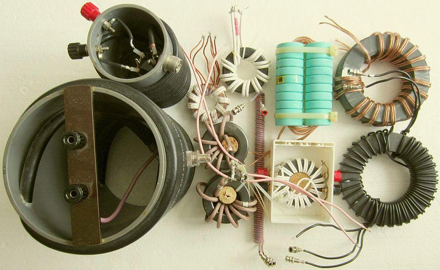
Many types of baluns tested with FC-4.
 The tuner is designed for end-fed antennas, bu toften hams use a doublet with open feedline or ribbon. Connecting a symmetrical system directly at antenna outputs A and B (2 wing nuts) works, however it is better to do it differently. Use a current balun to couple unbalanced output of the tuner to that antenna system.
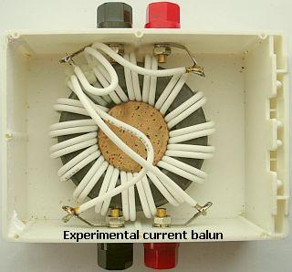
A symmetrical antenna system coupled with current balun.
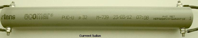
For experiment, I made (fig») an experimental current balun with TEFLON insulated wire and a junkbox toroid of unknown ferrite material. It proved to be suitable for testing. Better is to use a Amidon/Micro Metals toroidal type FT-240-K, AL = 4.9μH/turns², so one can achieve a high μ with few turns.
A toroidal core has the property that a large choke reactance is obtained with a small size, so that common mode currents remain low. The currents in the wires are almost equal and opposite, ultimately the flux is also small. If one ensures that the reactance of the windings is much larger than that of the antenna system, the core will have less chance to become saturated.
Example with FT-240-K toroid: 10 turns = 10² × 4.9 = 490 µH = 5700 Ohm on 160 m!
Heathing of the core is more due to the RF warming up current through (too thin) wires of the balun. With the differential-mode current, the respective flux is virtually zero, so that the ferrite does not have any influence on the characteristic of the transmission line. That is the theory because in practice, performance depends on construction, insulation of the windings and their mutual distance.
ANTENNA OUTPUTS A en B
 A dipole or ladder line can be connected across antenna terminals A and B, but there is a difference of tuning when A or B is grounded..
Schematically (f«ig) A or B are grounded in like manner, but on some bands more antenna current occurs at only one switch position. That's probably because A and B are not grounded via a similar path.
The image .shows (fig») that most of the difference arises on the 160 m band.
So it pays to try in which position of the switch most antenna current is obtained.
To expose the difference between tuner without balun and with balun a test was done in accordance with the («fig) image. JC-4 was connected to a 2 m long ladder line followed by a "standard" voltage 1 ÷ 1 balun and then passed to a professional 50 ohm dummy load. Incidentally the test is was also done with a voltage 4 ÷ 1 balun with almost the same results in terms of difference in balance or imbalance. The test shows clear that a current balun contributes a lot to equal currents in both conductors of the feeder. Furthermoer one can observe that the higher the frequency the more the imbalance. Other JC-4 owners report to me that RF feedback in their own equipment was reduced or even was solved with the current balun.
The aforementioned experimental balun made with an unknown type ferrite toroid works great but is an uncertain element to readers of this article. Because FT240-43 toroids are well known and be more available, I used them for further experimentation. Teflon insulated wire is not easy to obtain in contrast to 50 ohm PTFE coaxial cable and that was used for the baluns. The short coaxial cables have negligible loss and any small impedance transformation caused by the current balun is irrelevant because the tuner will compensate. Two cables in parallel have an impedance of 2 × 50 = 100 Ohm. The windings do not need of any specific characteristic impedance but this greater value is more favorable for a ladderline connected to a multi-band system. The feeder almost never presents a uniform load to the balun. As the operating frequency changes, the balun load impedance can change from several thousand ohms to a few ohms. The balun will pass the impedance through and 1 ÷ 1 baluns are generally much efficient and have a wide operating impedance range. They provide better balance, often have lower loss, tolerate load impedance and imbalance variations much better than voltage baluns. Without exaggeration, one can say that with a random length of the ladder line a 4 ÷ 1 balun has twice as many losses as a 1 ÷ 1 balun. In case of low impedance much current flows through the relatively thin inner core of the Teflon cable and it can be pretty hot.
Upper left a 1 ÷ 1 current balun which usually works well with any ladder line antenna system. If no match can be found, one may use an additional switch to select a 1 ÷ 4 balun. Remember: 1 ÷ 1 baluns are generally much more efficient and have a wide operating impedance range! The inductance of ten turns is about 200 µH. That might be inadequate for some antenna systems, but at present I do not have (yet) other ferrite material of a high μ and suitable for high power output. For the time being I use for each branch 3 × stacked FT240-43 toroids.
 |
 |
If one chooses for "A" or "B" of the controlbox, mostly there is a difference of maximum antenna current or no equal current in both conductors of the feeder.
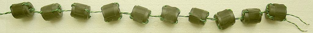
FERRITE PIPE
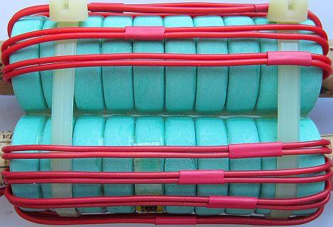
Smaller ferrite toroids can be used for assembling pipes to obtain more inductance with less turns. One pipe of the test model has just over 650 µH with 7 turns. The wires are Teflon isolated for arcing protection. The transmission lines are connected in series to increase the impedance. The system is a 1 ÷ 1 balun of random impedance to feed a random ladderline with a random dipole.
This type balun was so far the best. Unfortunately I have no information about toroid's type, because the ready-made construction came from a flea market and was at home dismantled for experiments.
In fact the principle is the same as previous construction with two toroids and coax cable and also with the following one toroid balun.
ONE TOROID
With one toroid the second coaxial cable or the second set windings should be wound in opposite direction, however in magnetic terms, the wires on the toroidal are installed in a correct direction.
C CORE CURRENT BALUN 1 ÷ 1
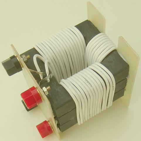

With C-cores from old TV's a 1 ÷ 1 current balun was made. Only 20 windings with Teflon insulated wire could be applied, but the inductance was 253 μH, a suitable value for many all-band antenna systems. At 80 m it is an impedance of ≈ 5800 Ohm. Currently an ACOM 600S amplifier is used with mostly 400 W output, but if the maximum of 600 W is used, the core of the current balun remains cold. It is used with the antenna shown above.
THE BEST UNTIL NOW
CURRENT AT INPUT AND OUTPUT OF JC-4


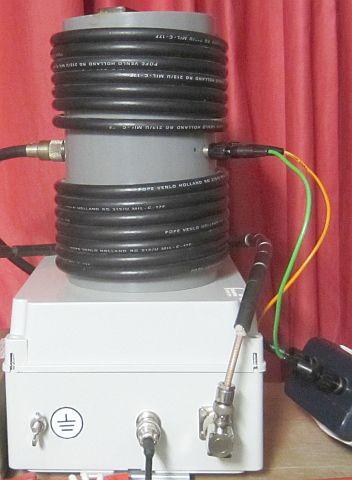
After a lot of experiments with various baluns and line filters in combination with 400 W ouput or more, it appears that an asymmetrical ATU works best with a symmetrical antenna system when a current balun is used at the input and at the output. The current balun at the output becomes less critically because it is actually relieved by the line filter at the input. For years I had a ferrite rod with a bifilar coil made with enamel wire covered with Teflon (PTFE). Without line filter at the input of the tuner, the rod became warm on some bands, but remained cool with an installed line filter at the input.
  The construction as shown in the image on the right. See also my article 'Coax Balun' |
 |
The balancing of both baluns do not differ much from each other.
A coax balun and ON7FU balun are compared with my current (fig») antenna. The test was done with 100 Watt and the balun between JC-4 and the RF current system with two meters. With respect to transfer asymmetrical into a good symmetrical system it can be seen that a slight difference exist between both baluns.
The current in the two conductors of the open line is not always the same because, although my dipole is symmetrical in length, electrically it does not have two equal halves on all bands.
The coax balun has no core and is constructed as 1 ÷ 4 balun, but that only applies if the output is loaded with an induction-free 200 ohm load. With every other impedance no 1 ÷ 4 impedance transformation occurs but it is even possible that it is transformed down! This device works optimally because the shielding at the output, the center of the load, is grounded.
Because no core is used, one does not have to worry about whether the core material is suitable for the transmitting power on the relevant amateur band.
You can consider this air balun as a very good transition from asymmetrical to symmetrical and the difference with ON7FU's 1 ÷ 1 balun is small.
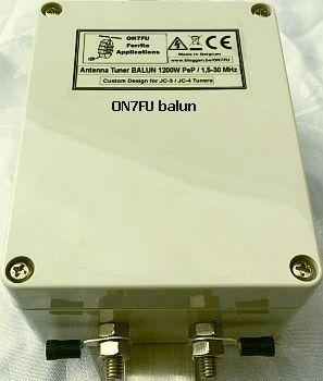
This balun supplied by Stockcorner is made from mix 31 ferrite and is according to the affixed sticker suitable for 1200 Watt PEP ouput power.
For about an hour I tested this ON7FU balun with 500 to 600 Watt as follows:
Always change bands and have the JC-4 tuned. That works quickly with interruptions to change the band on the set and activate the tuner. In my opinion, this method can be compared to an intermittent transmission such as an operator who performs a SSB QSO for about an hour.
The plastic housing of the balun became warm and that is probably due to the heating up of the ringcore (toroid).
It is explicitly stated that the housing may not be opened. That probably doesn't make sense either, because the inside is properly sealed with two components to keep moisture out.
Given the result of this test, the question is whether the balun is suitable for a contest station that works with 1200 Watt PEP. It will not be a problem for the more common QSO's. Furthermore, the balancing is good.
So far it works best with my antenna and an air-wound coaxial 1 ÷ 4 balun at the output and line isolators (choke baluns) at the inputs. The coax can be wound on two separate tubes, but it can also be on one tube, but then one of the coils has to be wound opposite.
It is important that at the entrance the outer screen of the coaxial cable (see above) is connected at a large metal mass, for example as done here, on the pipes of the central heating system.
COMPARISON OF AT-120, JC-4, S-Match
Set-up used to determine the mutual difference.
AT-120, JC-4, and S-Match are compared with my antenna («fig) by measuring the antenna current at the same point in the two conductors of the ladder line. Due to folding back a part of the antenna, the current in the feedlines are not always equal. The higher the frequency the greater the difference is. In contrast to the AT 120, JC-4 was able to match for SWR = 1.
Efficiency of JC-4 is better than an AT-120, but the difference is greater in the higher frequency range. On 30 m the AT-120 could not find any match, JC-4 had less difficulty, but the S-Match with his roller inductor did clearly better.
Not much difference is between JC-4 with current balun and symmetric S-Match. An exception is 160 m; the antenna for that band is too short and efficiency of the JC-4 is clearly less. The automatic tuner works with steps and my S-Match is continuously adjustable. Further the problem is caused by the 6 Ohm input impedance of the feedline line on 160 m. With such impedance many ATU's have a low efficiency. Each antenna tuner has the property that at a certain frequency and a certain antenna system, adjustment fails or efficiency is disappointing. It is due to the components used, the matching range, or way of construction.
JC-4, S-Match. The difference between JC-4 and S-Match was reduced when the ribbon line was lengthened or shortened. Apparently for both antenna couplers the input of my 10 m feedline was an unfavorable impedance on 160 m.
JC-4, AT-120. If the ribbon line was lengthenend or shortened JC-4 reached almost always SWR = 1 while AT-120 often mathes to SWR = 1.5 - 1.7 and repeatedly the efficiencey was less than JC-4.
G5RV, ZS6BKW. My antenna behaves the same as G5RV/ZS6BKW and a JC-4 will match both types without any problem.
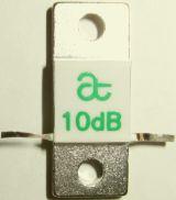
ATTENUATOR 10dB, 100 W/50 Ohm
Earlier it was reported that the transmitter temporarily is loaded with a highly fluctuating impedance during tuning. In addition, one has to reduce the drive for 10 - 20 W by turning a potmeter and the setting accuracy for that power is often different per band.
Will be continued for new developments.
![]()
