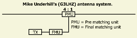
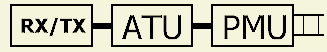
G3LHZ's SYSTEM FOR MATCHING ANTENNAS
Published in (VERON's) ELECTRON No. 12 of December 2020 page 585.
 |
 ? ? |
 |
INTRODUCTION
It was almost for 40 years that PAØSE (SK) in Electron magazin of VERON (association for experimental radio research) paid attention to G3LHZ's special system for matching short wave antennas. It is also an interesting way to feed our HF antennas.
Hence, it might be a reason to point novice hams to the system as well.
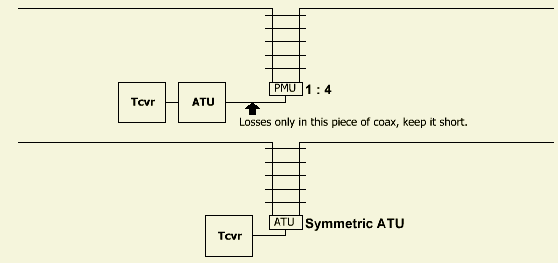
FMU FOR HF BANDS
 When feeding a random dipole with a coaxial cable, a high loss standing wave ratio (SWR) occurs in the feed line. By matching the antenna system in two steps, G3LHZ calls them: Pre-Match Unit (PMU) and Final-Match Unit (FMU), the SWR is reduced to a lower value. However, that value will then be reduced to SWR < 20! That is a bit of a shock, but the losses in the coax cable are considered acceptable.
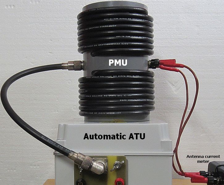
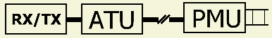 The PMU is applied at the feed point of the antenna and the FMU inserted between transmitter and coaxial cable.
The antenna tuner (ATU) must be able to reduce SWR = 20 down to SWR = 1 in order to load the transmitter with an correct impedance.
The advantage of the system is that an ATU can be simple and after many experiments G3LHZ came to the conclusion that with an L network it is always possible to tune or match an random antenna.
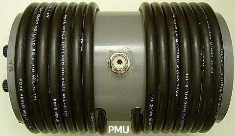
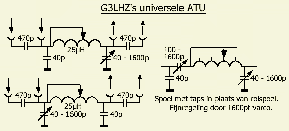
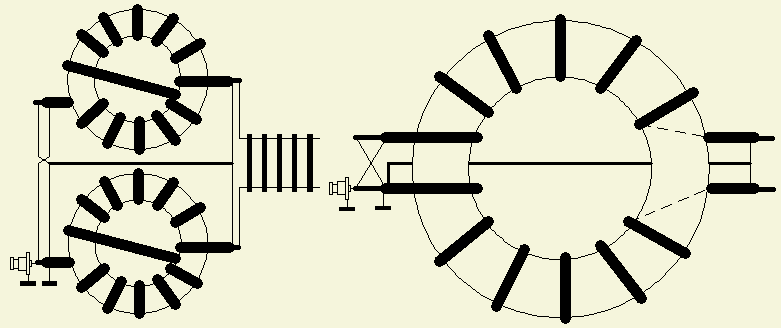
Irrespective of the feeded antenna and taking into account the minimum capacitance of the capacitors, stray capacitance of the wiring, etc., according to Mike, the image opposite is the universal ATU (PMU) for the amateur bands. Eight different configurations are available via switches or sockets to be fitted.
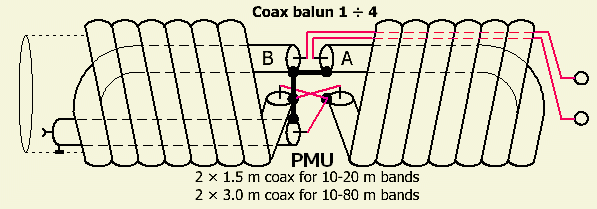
PRE-MATCH UNIT
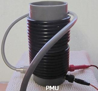
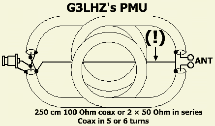 The Pre-Match Unit consists of two approximately 250 cm long 100 Ohm coaxial cables. To obtain 100 Ohm, one can connect two 50 Ohm cables in series per branch. This is done by soldering the screen on both sides and using only the inner wire as conductors for the PMU.
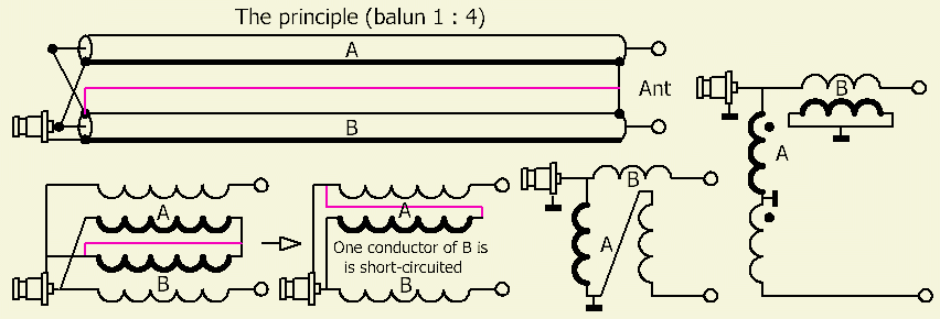
The circuit is very similar to a 1 : 4 coax balun or transmission line transformer, but the center of the output is connected to the common ground. In this way the antenna is fed symmetrically with respect to ground.
At the bottom coax cable, the input and output are in phase, actually no need to roll up. At the top cable, the difference between input and output is 180º.
One conductor of B is short-circuited and therefore does not participate. The principle is shown on the right. The other conductor of B could be regarded as a so-called "compensation" coil.
NOTE: The transfer ratio of 1 ÷ 4 only applies if output of PMU is loaded with a inductance-free film or carbon resistor. With 50 Ohm cables it is 4 × 25 = 100 Ohm and with 100 Ohm coax it is 4 × 50 = 200 Ohm. There is no quadrupling for any other complex load. It is even possible to transform down, because the coax cables act as an impedance transformer. The result depends on the operating frequency.
The PMU can best be regarded as an effective way for transforming asymmetrical to symmetrical.
FINAL-MATCH UNIT
Instead of G3LHZ's FMU, one can also use our frequently used T-match antenna tuners or other asymmetrical ATU's for the HF bands!
In plaats van G3LHZ's FMU kan men voor onze banden ook de bij ons veel gebruikte T-match antennetuners of andere asymmetrische aanpassystemen gebruiken!
PRACTICAL EXPERIENCE
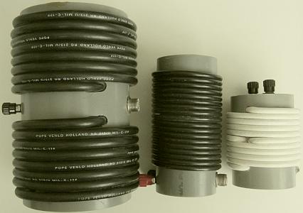
The original PMU was made with 100 Ohm coax, but because of the lack of that type it was done with 50 Ohm coax and that it works well. It is practical to arrange both cables in the same shape, but with opposite windings. It is important to keep all ends as close together as possible and the drawing shows an example.
Since PAØSE's publication I have been working a lot with PMUs. Usually not at the feed point of the antenna but at the input of a ladder line to a random wire dipole. It is almost always possible to match the antenna on all HF bands with simple LC networks. Especially when the antenna is close in size to a G5RV or ZS6BKW.
A PMU turns out to be an almost ideal symmetry transformer with very little losses. If the coaxial cable between asymmetrical antenna tuner and PMU is kept short, the loss of the system compared to a symmetrical antenna tuner is minimal.
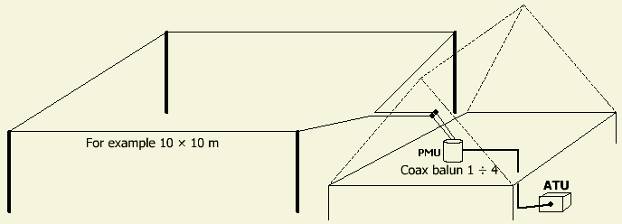
ANTENNA EXAMPLE
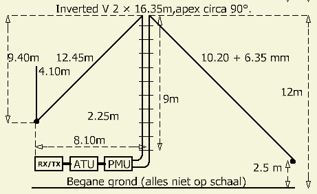
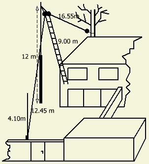
Over the past 40 years lot of wire antennas have been installed in my side yard and backyard in an attempt to use the most of the limited space. Finally it became the showed antenna. The backyard is too short to fully extend one half of the dipole. To compensate for the too short length, a vertical aluminum tube was set up as an extension at the end.
With a manual or automatic asymmetrical antenna tuner and a short piece of coaxial cable between tuner and PMU, the antenna is used from 10 to 160 m. On the 160 m band, the short antenna has a very low impedance (≈ 6 Ohm) and therefore a lot of transmission power is converted as heat in the ATU. Nevertheless, it is possible to make contact with other amateurs on 160 m within Europe.
CURRENT IN FEEDER
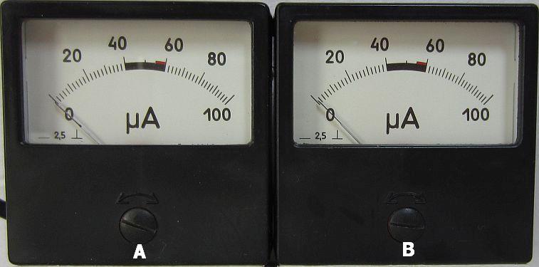
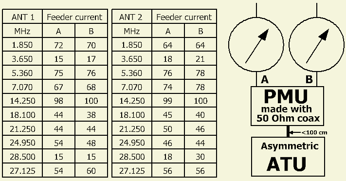
The current in both conductors of the slotted feeder line was measured on all bands of the antenna shown above and a variation thereof. The PMU (fig») has been in use for over 30 years and was constructed and assembled with RG 213/U 50 Ohm coaxial cable. The antenna current meter is DIY and ensuring that both systems are as identical as possible. The deviation is approximately 1 scale division.
The table shows that the PMU provides a fairly good symmetric ouput. Major differences arise due to the electrically asymmetrical antenna and, or due to the non-negligible capacitance of the windings.
Both halves of my wire dipole antenna have the same mechanical length, but given the setup, the capacitance to ground is different and that creates a difference in electrical length. This not have the same effect per amateur band. It is therefore possible that the HF currents in the feeder line are not always exactly equal to each other.
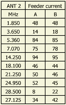
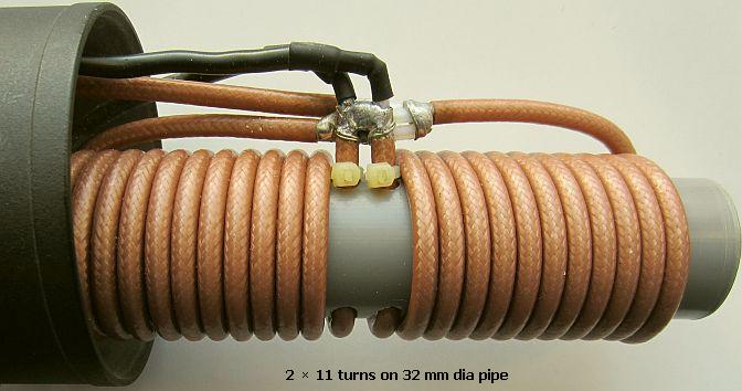
Another additional test with the antenna was done with a smaller size PMU made of 50 Ohm PTFE coaxial cable with 2 × 11 turns on a 32 mm diameter PVC pipe. It can be seen that most likely the capacitance of the windings caused the remarkable result on the 10 m band. Furthermore, the percentage difference in current is not that different from the two other tests.
It is best to keep the distance between ATU and PMU as short as possible: ATU - PMU<100 cm. Most asymmetrical antenna tuners used by radio amateurs, such as T-match and Pi-filter, are suitable for matching the feeder line with antenna. If it does not always work, it is often sufficient to extend or shorten the slotted line 1 - 3 m. If more loss is accepted, the coaxial cable between ATU and PMU can be extended. If a ribbon line is awkwardly too long, one can wrap a section with space around a pipe. That part funktions as an extra line insulator or choke balun.
If there is any imbalance at the output, it can often be corrected by swapping the connections of the ribbon cable or open line
RING CORES (FT240-43)
A smaller PMU can be composed with ferrite toroids. The problem is to obtain the right type. With 100 W transmission power, almost "everything" works, but with more power such as 400 - 800 W the unsuitable types can become hot with prolonged load and even explode. The toroids that were recommended to me turned out to be too hot after thorough testing. You should know for yourself, but I wouldn't use ferrite toroids for a PMU. Moreover, it is cheaper without it.
FINALLY
 If you have an symmetrical antenna system with an asymmetrical antenna tuner, the Pre-Match Unit (PMU) of Mike Underhill (G3LHZ) between tuner and open line, ladder line or slotetd line, makes it possible to match the antenna. The symmetry is decent and losses compared to a symmetrical antenna tune system are nil or negligible.
If you have a symmetrical antenna system with an asymmetrical antenna tuner, then with the Pre-Match Unit (PMU) of Mike Underhill (G3LHZ) between tuner and open line, chicken ladder or ribbon cable, matching antenna is possible. The symmetry is decent and losses compared to a symmetrical antenna matching system are nil or negligible.
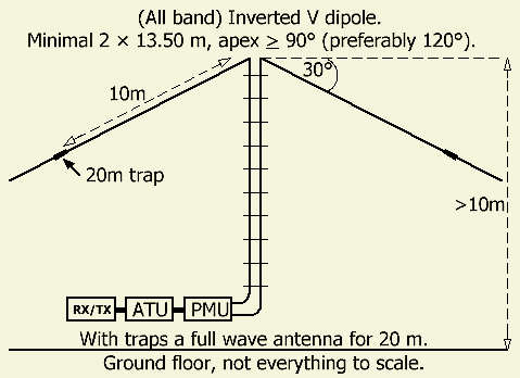
Any dipole («fig) fed with an open line can be used with a suitable adjustment system for all HF bands. Qua efficiency, it is recommended to choose at least 13.50 m for both antenna legs. Try to keep the height at least 10 m above the ground.
If you work a lot on the 20 m band, by installing 20 m traps («fig) you can ensure that the dipole becomes a full wave on that band, so that you have some gain compared to a half wave dipole for 20 m band.
If you have a small backyard, it is often better to install a small horizontal loop or delta loop antenna. Such loop antennas, in combination with a suitable antenna tuner, are good all-band antennas and as bonus less interference.
![]()
