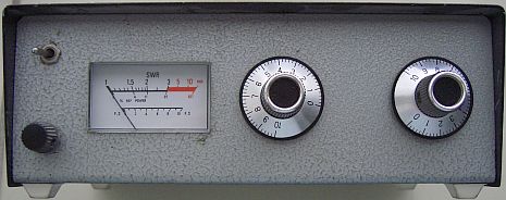
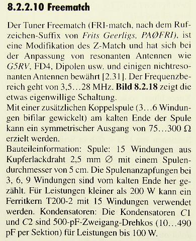
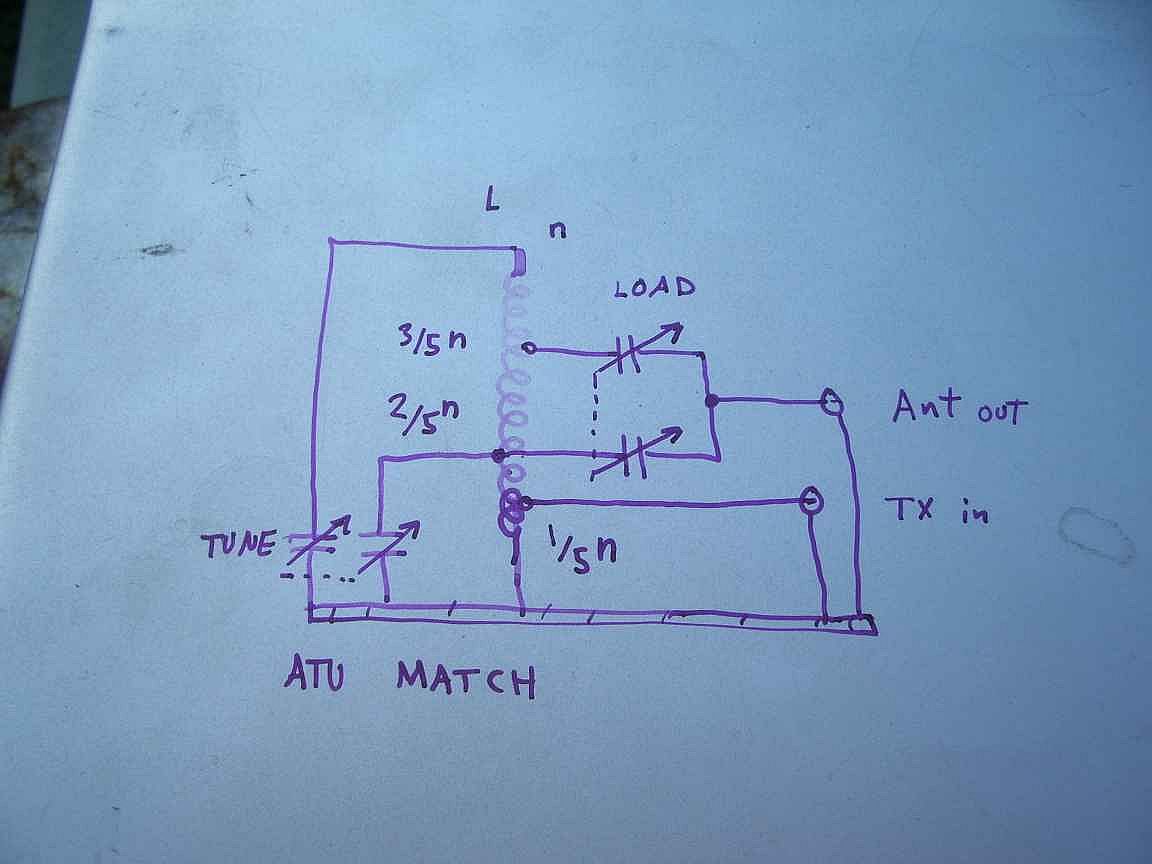
FRI-Match ATU, a single-coil Z-Match type:
(Freematch line matching unit etc. published in RSGB's RadCom 1989 july and Rothammel's Antenna Book).
![]() 30 -sep-2022
30 -sep-2022
Antenna tuner for 10 to 80 m, but also suitable for 50 and 70 MHz bands.
DESIGN
This ATU, I call my design FRI-Match, has been devised in 1972 as an unbalanced tuner for improving the SWR at the transmitter end of coaxial feeders to resonant antennas (eg verticals, dipoles, trapped dipoles, G5RVs, Yagis, loopquads etc.). Basically the same features of the current internal automatic antenna tuners.
PAT Hawker (SK) wrote in Radio Communication: "surprisingly, it seems to have attracted relatively little attention when it featured in TT July 1989. In view of the current interest in this approach it seems worth repeating this pioneering 1989 item".
|
|
|
It is a modified version of the well-known Z-match and is designed as the result of experiments in reducing the SWR on the five HF bands between 3.5 and 28 MHz (incl. the WARC bands) without the necessity for switching coils and with a minimum of knobs.
Tom Seed, ZL3QQ, has published a basically similar approach with a detailed explanation of the theory of operation in BREAK-IN March 1992. Bill Orr, W6SAI, has featured this ATU in the August and September 1993 issues of CQ.
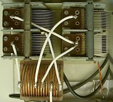
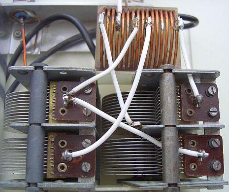
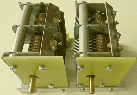
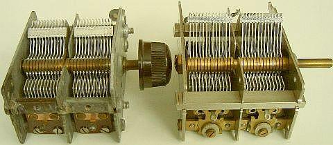
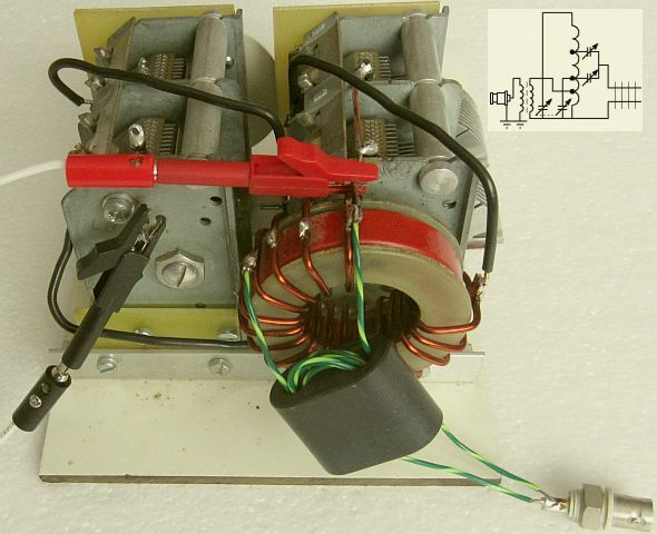
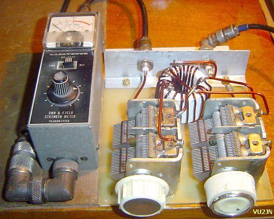
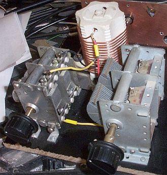
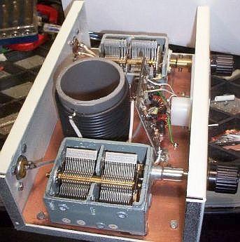
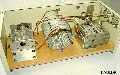
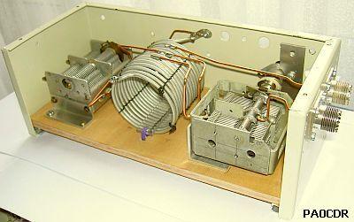
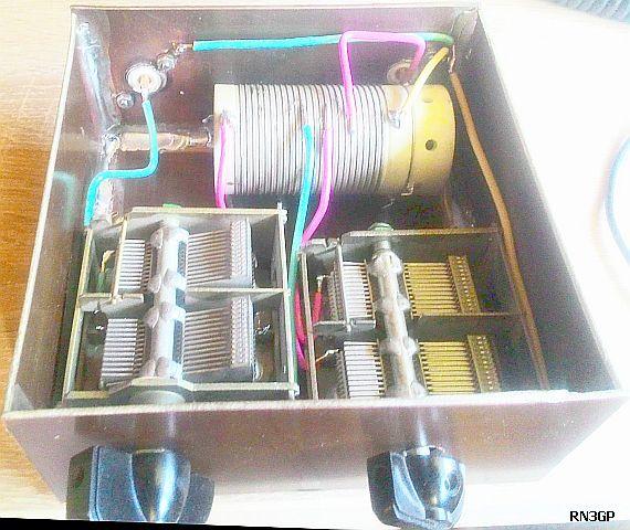
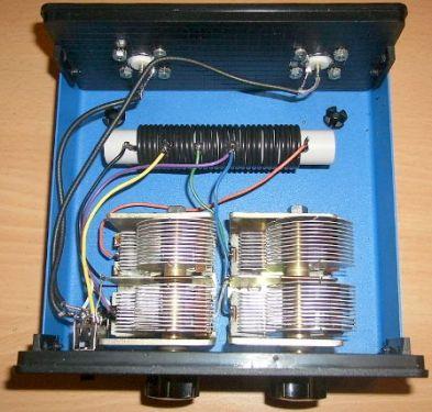
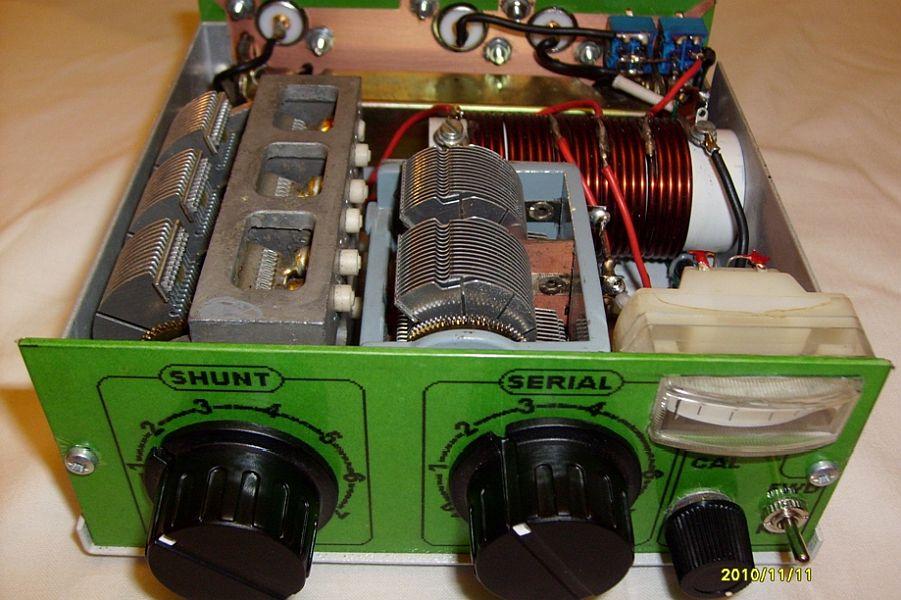
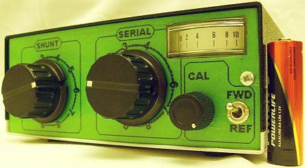
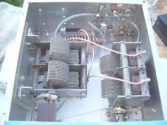
After experimentation with various antennas and complex loads, one 5 - 8 µH coil turns out to be the best tuning system for 10 to 80 m. The efficiency of the tuner is good, because it can be considered as an auto transformer with inductive and capacitive taps on the coil. Originally the design was a three knobs tuner (the left model). The results of further experiments were the middle and right model (with two knobs). The twin varicap has almost the same effect as the switched capacitor at the input of the left model. So a switch could be saved.
One of my first constructions was with two tiny plastic varicaps as used in portable AM radios.
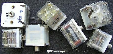
Although intended for QRP, they were often suitable for even 100 W if the loaded impedance was relative low, e.g. very close to 50 Ohms. My QRP ATU no longer exist, but accidentally PA4M build a device (fig ») almost similar to my former unit.
.
SYMMETRIC OUTPUT
Essentially the FRI-match is a 'kiss' approach, cheaper and almost fast as an automatic ATU provided that the calibrated settings on each band for minimum SWR are known so that the capacitors can be quickly reset
In practice the ATU has proved more flexible than expected and in many cases permits matching to non-resonant antennas.
An antenna with an ladderline can be tuned by installing a coupling coil of 3 - 6 turns over the lower part of the coil. This number is an average because it depends on the impedance of the load. The capacitive coupling of both coils disturbs balancing and the extra coil reduces the efficiency of this tuner. The result strongly depends on the correct number of turns inorder to match the impedance at the beginning of the open line. For example, if it is a high impedance and there are too few windings, a SWR = 1 can usually be found, but less energy enters the antenna. Given the uncertainties listed, I cannot recommend this system. Nevertheless, you can experiment with the number of windings for a maximum current in feeder to your antenna system.
However, it should be noted that this design couldn't satisfy all possible conditions such as random length wires and antennas. This can sometimes be overcome by increasing or decreasing the length of the coaxial feeder or ladder line and/or reversing the input/output thermals of the ATU. To meet all possible matching conditions a more complex arrangement should be necessary.
I use a FRI-match almost exclusively as an asymmetrical tuner for coaxial feed antennas or as a tuning unit between transmitter and a HF amplifier to be tested. If a symmetrical antenna system needs to be adjusted, I use (fig ») it in combination with a suitable balun at the output of the ATU. See for example coax balun.
COIL INFORMATION
|
COIL |
Wire diameter of at least 1 to 2 mm. |
||||
|
Long |
4.5 cm |
5.5 cm |
|||
|
ID |
5 cm |
4 cm |
|||
|
Turns |
15 |
15 |
|||
|
Taps |
3, 6, 9 |
3, 6, 9 |
|||
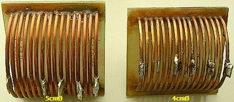
The coil is made with: 15 turns of 2.5 mm diameter enamelled copper wire or 6 mm² tinned copper wire, 4.5 cm long with 5 cm ID or 5.5 cm long with 4 cm ID. Taps on 3, 6, and 9 turns from earthy end.
CALCULATION OF THE TAPS
If random sized 5 – 8 µH coils with n turns (see PE1ADY's ATU) are used
the taps for equal efficiency on all bands should be at:
|
Coil |
Random size but: 5 – 8 µH |
|
Turns |
n |
|
Tap 1 |
n ÷ 5 turns from earthy end |
|
Tap 2 |
2n ÷ 5 turns from earthy end |
|
Tap 3 |
3n ÷ 5 turns from earthy end |
Example of calculation: suppose you have a coil with a small diameter and 30 turns, the first tap is at 30 ÷ 5 = 6 turns, the second tap: (2 × 30) ÷ 5 = 12 turns and the third tap: (3 × 30) ÷ 5 = 18 turns.
After my publication in RadCom, others also experimented with one coil, but the taps are different. Unfortunately, the authors do not explain how and why the relevant taps were chosen. If the efficiency is not taken into consideration, then indeed with other taps on the coil a SWR = 1 can also be achieved.
In my design, every effort has been made to keep equal efficiency on all bands for matching a 50 Ohm load!
Extensive experiments for at least six months have yielded my found turns on the coil. Those tests were repeated two years later and the first results were confirmed again. It turned out that the efficiency with the found taps was on average the best. Various loads in the form of antennas or combinations with resistances per band have been tried and attention was paid to efficiency and match. With this design and formula for the taps, the loss of the tuner on all bands is almost even and small. If you choose different taps, then it is possible that all bands can be matched but with less efficiency on some bands.
 You can test («fig) your current ATU between your transmitter and a 50 Ohm load. Match the system, measure the power in the dummy load with and without tuner and then check the difference.
MATCHING
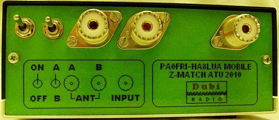
Each side can be used as input, but in general the right figure will work best in terms of efficiency. If no adjustment can be found, choose the left figure. You can do this manually by swapping the input and output or with a double switch (another button extra!).
SYSTEM
Although this ATU was actually intended to get a low SWR for the band limits of a resonant antenna, in practice it turned out that much more is possible. However, remember that this ATU has its limitations, just like other antenna tuner units.
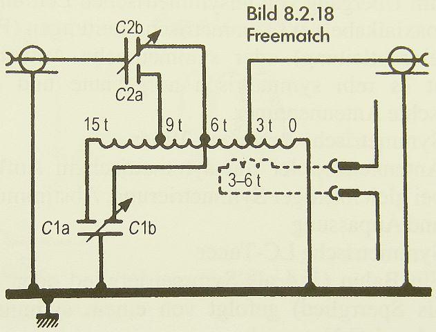
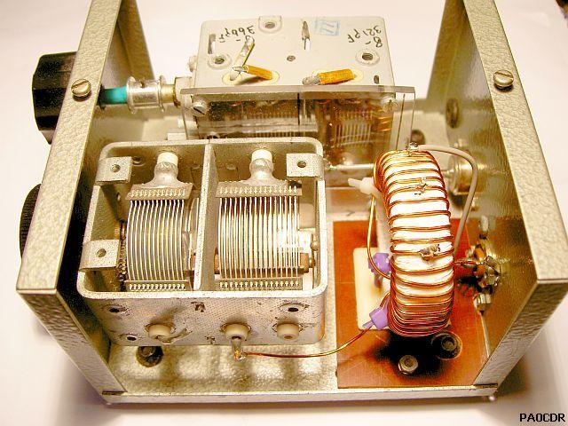
The operation of the coil is rather complex. Most bands are tuned by windings to the second tap. The complete coil are for 80 m and 20 m. The twin variable capacitor plays an important for tuning the 20 m band and usually two matches can be obtained on that band. Choose the point where the capacitor has the largest capacitance. With the capacitor almost at minimum capacitance the 40 m and 10 m band are covered.
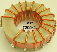
RING CORE/TOROID
|
|
|
Ring core: T200-2 |
|
Turns |
||
|
Taps |
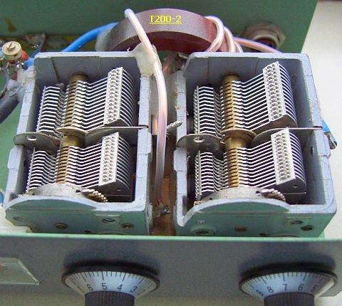
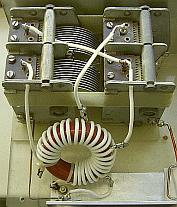
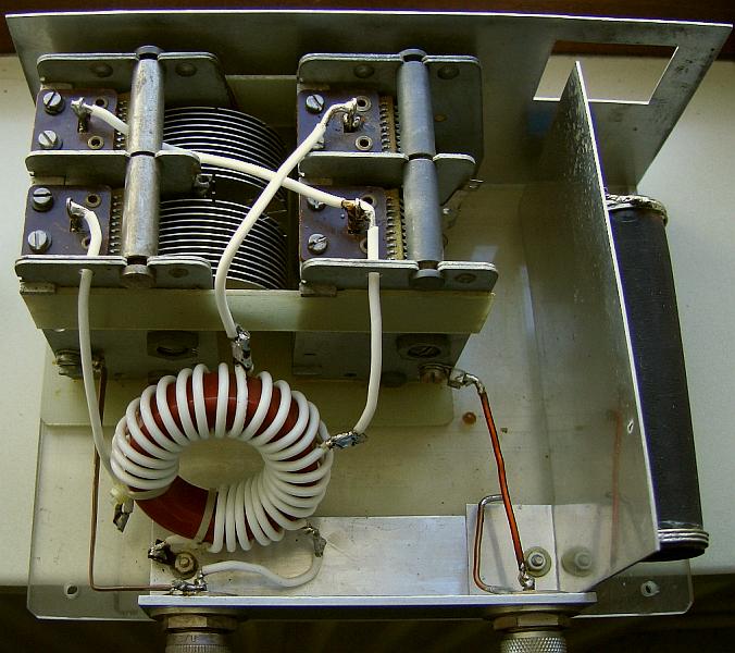
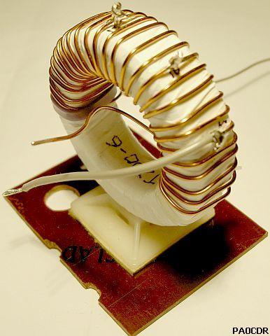
A ring core is self-shielding because it's low external field, so facilitates compact construction. For ≈ 400 W power, a T200-2 toroid can be used with 25 turns on 75% of the circumference
Taps 5, 10 and 15 turns from earthy end. A 5 to 8 µH coil seems to be the best as the result of experiments.
Before winding, several layers of Teflon plumbing tape must be applied to the core, to insulate it from the coil-windings. Another method of insulation is to cement two flat isolating washers (e.g. made from bare glass fibre board, see figure) on each side of the bare core. Apply a small quantity of super glue, possibly only a few drops, around the sides of the core. Work swiftly; the glue hardens quickly. The glue prevents the washers from moving out of alignment while the core is being prepared for winding. For a T200-2 core, the inner diameter should be 28 mm and the outer diameter 55 mm. With this last construction it might be even possible to use bare copper wire for the windings.
CAPACITOR
With many antenna systems these varco's from old AM radios are suitable for 400 W transmitting power!
Variable capacitors can be receiver-types twin-gang 10 – 490 pF per section, for power up to 400 W. For up to 100 W operation a T200-2 toroid and two air-dielectric variable capacitors salvaged from vintage AM radios can be used. If 2 × 350 pF capacitors are used the coil should be increased to about 8 µH. If 3 × 350 or 3 × 490 pF are used in some cases the FRI-match permits limited matching on the 160 m band. It will then still work on 10 m.
 Dual 2 × 470 pF variable capacitors discarded from vintage receivers are very suitable and in this design can handle 400 W or a little more with many antenna systems. The free space between a fixed and rotating plate will be approximately 0.6 - 1 mm. With the capacitor almost at minimum, the 40 m band is covered and therefore the smallest possible zero capacity is important. If it is too large, tuning on 40 m may or may not be successful. The 20 m range is largely determined by the variable capacitance between the second and third tap of the coil.
No malfunction occurs with 1000 W on 80 m, during a test («fig) with toroidal core and an antenna (fig») of 2 × 17.30 m, 9 m ladderline and 4 ÷ 1 balun! The ring core did not get hot, but the wire with PTFE (Teflon) insulation eventually did. This antenna system with coax balun and Fri-match was able to match all 8 bands (10 - 80 m) with a SWR = 1.
.
 Capacitors with a smaller plate spacing are suitable for around 100 W. Types of plastic are suitable for QRP sets. Values of 2 × 350 pF can also be used, but make sure that the coil is approximately 8 µH.
There are also small triple capacitors of 3 × 330 pF. One can use according to («fig) the diagram, it is even possible that 160 m can be matched over a very limited area. The 40 m band is then often no longer to be found with plates turned out, but comes back by increasing the capacity while turning.
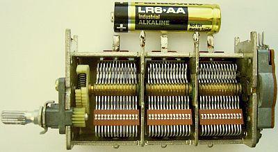
To give you an impression of the size, see a AAA battery along with an example of a small triple variable capacitor.
160 m
The 160 m band almost always falls outside the control area of this tuner. If you want to have that strap on, you need a coil with more self-induction. The "formula" for the branches remains valid. Only a part in the 10-20 m range will be missing. The range then becomes approximately 30 - 160 m, but it can be better than expected.
ANTENNAS
 Antennas such as G5RV with balun, W3DZZ, FD3 and FD4, trap verticals and Yagis can be easily adjusted with a FRI Match. If you make an FD3 or FD4 yourself and use this tuner, you can as well place a 1 ÷ 4 balun with good results. That can be made yourself with a toroidal core, but better is a coax balun possibly a smaller model with a thin coax cable according to this article balun. The balun mentioned can also be used for feeding an antenna with an open line.
A good adjustment and radiation efficiency is achieved if the open line plus dipole half is approximately 27 m. Make sure that the antenna is not smaller than 2 × 13 m. With this system and an antenna of 2 × 13.50 m I have worked with good results for years. When visitors saw my antenna, their comments were often: "You do have a strong signal with such a short antenna and that with 100 W"!
 If the feeding line becomes too long in your situation, roll the rest as a ribbon line ("fig") on a tube.
If you have an old-fashioned 300 Ω ribbon line, it can also be rolled up like a film roll (fig »), see also universal dipole. With both methods you actually get the effect of a mantle choke as an extra.
In practical use this tuner adjusts more than originally intended. It is just a matter of playing with both capacitors or connections. You have to find out and experience for yourself. An example of how it is possible is the adaptation of a wire antenna as shown opposite. The tap with the best adjustment must be determined experimentally. If you always use the same antenna, it only needs to be done once. It is also possible that an adjustment is successful by connecting the antenna directly to one of the taps.
UNIVERSAL SYSTEM
|
|
 4 : 1 Balun/trafo |
 1 : 1 Balun/trafo |
More is possible with this design, a combination of an asymmetrical and symmetrical tuner. The variable capacitors must be isolated mounted. A coaxial cable with antenna or a symmetrical line with antenna can be adapted at will. An isolation transformer (4 : 1) ensures that the 50 Ohm cable impedance is converted to a lower value so that the ATU can more easily adapt the higher impedances of antenna systems. Every tuner system has its limitations, but until now it was possible to tune my own W3DZZ with open-line power on all bands from 10 to 80 m.
On the left a well-functioning version with a ! : 1 transformer with a pig nose. With my current inverted V of 2 × 16.50 m it was not necessary to switch in and output terminals.
ROTHAMMEL ANTENNENBUCH
In the well-known Antennenbuch by Karl Rothammel, DM2ABK, Y21BK (SK) are a lot of information about antenna systems, tuners, coaxial cables etc. It is a good informative reference work. This tuner is at present one of the regular topics of this book.
BTW the editorial team will be continued by DJØTR.
REVIEW
The experience and judgment of professor R. Jayaraman, VU2JN.
To make a long story short, my Fri-match ATU was completed in March 2011, nearly half a century after I first thought of building an ATU! Fig. 4 shows a photo (fig») of this ATU. It has just 2 controls, and no rotary inductor. It outperforms the conventional Z-match with regard to ease of tuning and tuning range, and is almost as good as the SPC Transmatch. And interestingly, so long as the Fri-match ATU is able to match an antenna within its tuning range, it is able to bring down the SWR to exactly 1.0. This is something that I had not expected from a 2-knob ATU that is free of the burden of a variable inductor! No reduction drives are used in this ATU. Though the tuning of the condensers is very sharp, it is manageable, even for a person aged 75 years! An analog SWR bridge is needed for tune-up. A point to be kept in mind is that, if one of the condensers is very much off-tune, tuning the other condenser would not produce any dip in the reflected power. Therefore, in the absence of calibrated dials, visual monitoring of the condensers is necessary. The body of one of the condensers has a RF potential but, since it is tied to the transmitter output, there is no hand-capacitance effect.
The Fri-match ATU sits to my right near the front edge of the operating table, not far away from the FT-840 transceiver. From the antenna switch, a 70-ft. length of RG-223 coax feeds a 40-metredipole antenna, and a 50-ft. length of RG-213 coax feeds a HY-GAIN 12AVQ 3-band ground-plane antenna. The ATU enables me to use the 40-metre dipole on 20, 40 and 80 metres, and the 12AVQ ground-plane on 10, 15, 20 and 40 metres --all with a SWR of 1.0 as seen by the transceiver. So much so, the ATU is useful even when a resonant antenna is used for the band of operation. On 20 metres and the higher bands, I normally use the 12AVQ ground-plane. The only time I operate with a non-resonant antenna is when I use my 40-metre dipole on 80 metres. Signal reports then indicate that I am roughly 1 S-point weaker than similar stations using a 80-metre dipole. That's not bad, and I am quite happy with the performance of the ATU.
I recommend this ATU to all hams. When an ATU is available, we can fabricate a dipole, ground-plane or any other antenna simply to the dimensions suggested by theory, and dispense with the trimming of the antenna. In many situations, trimming of the antenna to lower the SWR is unscientific, because the problem is not in the antenna, but elsewhere! It is better to rely on the ATU to take care of the fine tuning of a resonant antenna.
-- VU2JN.
See the complete article by professor R. Jayaraman, VU2JN about the Frimatch-ATU.
PA1ADY
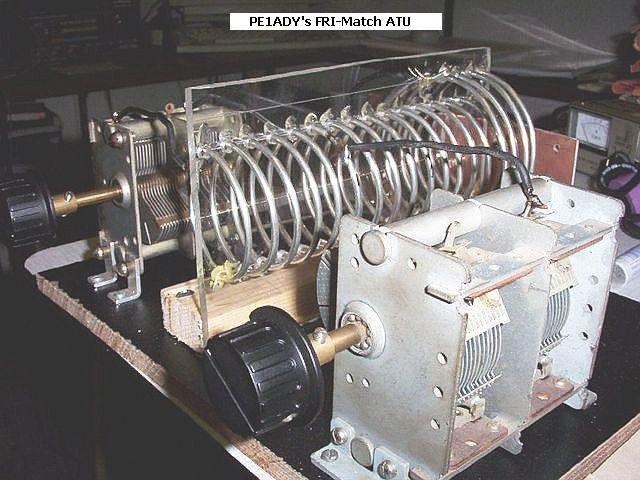
PE1ADYs FRI-Match ATU's.
PA4H
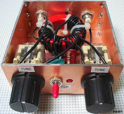
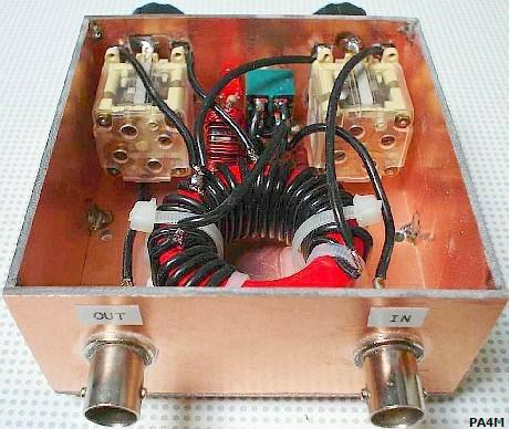
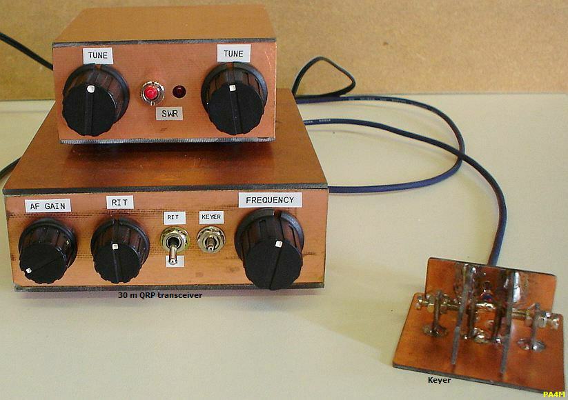
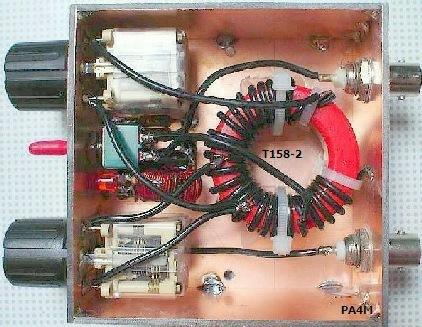
PA4M made the design with a built-in N7VE SWR indicator so that no separate SWR meter was needed. He uses his FRI-match with a DIY 30 m CW transceiver. He has not yet been able to test the efficiency of the tuner, but matching is very smooth. The toroidal core is a T158-2 because it happened to be present unused.
PAØCDR
PA0CDR also got to work and his email stated: "It works wonderfully, a very smooth tuning action with my Endfed that runs over the attics here. Great success ..!" A summary of his activities:
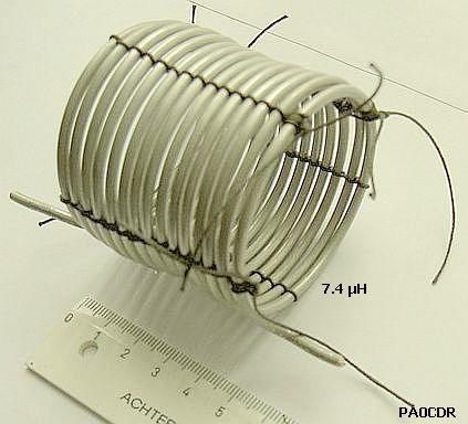
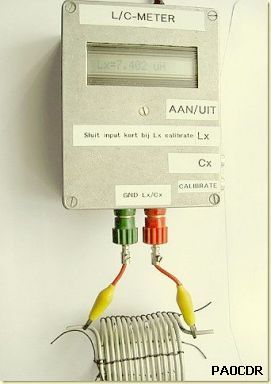
He made the air coil from 6 mm² installation wire because enamelled copper wire of larger diameter was difficult to get in his town. The wire is stiff, an adventage because it stays in good shape and is therefore suitable for air coils.
If he followed the winding details of this article, 15 turns on a coil diameter of 5 cm over a length of 4.5 cm, then there were some problems. The installation wire is supplied by the hardware store on a bundle with windings of unequal diameter.
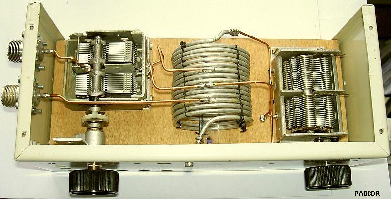
His version with a toroidal core also works well.
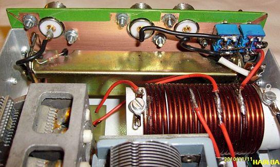
HA8LUA
HA8LUA:"I looked for a really little portable ATU which is very universal (can be used with all my field day antennas: doublet with ladderline, G5RV, FD3, verticals, etc.). A few years ago I built a Z-match QRP ATU for my FT-7 and it worked fine! I have a FT-897D now, that’s why I needed a 100W model. The Z-match principle was given for me and I read PA0FRI’s very-very nice article on his website. The result":
|
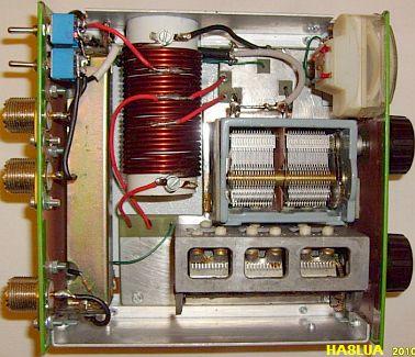
C1 3×450 pF |
 |
I have just made some initial, „cold” tests without real TX with power. I used different resistors (25, 50, 125 & 250 ohms) as „load” on the antenna shockets and an antenna analyzer on the input. The ATU seems to work, but the tuning on low bands was a bit difficult because of beeing very „sharp” (despite of the reduction driwe mechanism on the C1 & C2!). There seem to be a few „gray zones” on the low bands (40 m, 160 m), where is a bit difficult to get good match at certain load impedances. But it’s possible!
|
a "funny" ATU tuner
its a "FRI-MATCH!" my implementation by RALPH KLIMEK VK3ZZC OCT-2013
|
||
 |
 |
 |
| conductors are made from silver plated teflon coax outers off-cuts for the last word in low loss. see also the insulating shaft coupler |
bnc and so-259 mounted to copper flashing for a positive galvanic RF grade ground | the coil |
 |
 |
 |
| the rotors of my tuning gangs are positively grounded to frame by rotary straps. the insulator block adapts the 3/8 inch rotor shaft to 1/4 inch for front panel knob. | gang mounted on perspex plate | original brass wiper was just riveted to frame |
 |
 |
 |
| connect rotors to the capacitor frame for trouble free tuning. The brass block is used to contain and terminate the shaft grounding strap. I do not rely on the old wiper arrangement. You will have erratic tuning if you do. | positve grounding ensures trouble free operation |
I can never find a BNC-PL259 adapter when I need one, so I provision BOTH ! Always use silver plated connectors for RF if available. (it does make a differance ) |
 |
||
KØIYE
The FRI-Match Antenna Tuner By Frank Harris, KØIYE
Sometimes on I've had trouble getting some of my antennas to properly load the 15, 12 and 10 meter bands. My friend Jayram, VU2JN in India, sent an article he wrote about his new homebrew antenna tuner. It is a design originally developed by PAØFRI - hence the name "FRI-Match." Jayram is impressed by the ability of his FRI-Match to load his 40 meter dipole on 80 meters and actually talk to folks hundreds of miles away. My homebrew T-Match tuner can load a 40 meter dipole on 80 meters, too. But even though the transmitter doesn't overheat, the propagation is poor and no one hears me. To transmit on 80 meters I have to use the entire 40M dipole, coax and all, as a long-wire antenna with my entire 30 meter dipole in the backyard as a long-wire counterpoise.
In spite of the fact that I can't figure out how the FRI-match is supposed to work, I built one and am quite pleased with it. It is compact and does not have a variable inductor. You can use an air core or another fixed inductor. Jayram recommends using 5 to 8 micro henries total tuned with ganged 470 pF capacitors. For the inductor I used 26 turns on a T-200-6 (CWS, Amidon) large powdered iron core wound for a total of 7 micro henries. Once you know how many turns you need for the entire inductor, calculate each of the 3 taps on the coil by multiplying the total turns by the number shown below and divide by 5. I couldn't find 470 pF capacitors, so I used 365 pF caps which are available from RF Parts Company (RFparts.com).
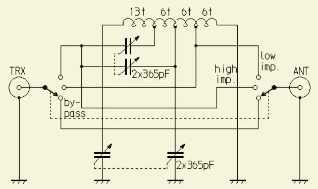
The FRI-Match circuit is shown below. One of my capacitors is two-thirds of a triple-gang 365 pF capacitor because I didn't have two dual-ganged caps. No matter. It works well, but I haven't tried it down on 160 meters. As Jayram suggested, I should have used heavier gauge wire, but didn't have any. However, that probably isn't important.
The input variable capacitor is floating and not connected to the aluminium ground sheet. The coil is mounted on a plastic insulating bracket. A short piece of RG-58 coax connects the coil to the output connector on the right. As is usual for me, I used scope and frequency counter probes to monitor the antenna voltage waveform.
One happy surprise is that, the FRI-Match not only tunes better on the high bands, it delivers more power to the antenna. The most dramatic example was on 10 meters. With my old T-Match on 10 meter sideband, I could only get 25 watts peak. With the FRI-Match I could tune it two ways. At one setting I got the usual 25 watts, but with the output capacitor rotated toward the other end of its range, I suddenly had 50 watts delivered to a 50 ohm dummy load or to my vertical antenna (ed. note: I also have trouble differentiating the effect of a dummy load from a vertical antenna). I am continually surprised by the effect that the antenna impedance has on the various transmitter amplifier stages. Logically, one would expect that only the final amplifier stage would be affected by the antenna loading. In practice, tuning and performance of earlier stages are also affected. Due to the low output of my 10 meter SSB driver, I believed that 50 watts output would be impossible on that band. On 20 meters, my output rose from 65 watts to 100 watts. Too bad I can't tune up some more sunspots!
![]()
![]()