ANTENNA CURRENT METER
![]() 20-Oct-2022
20-Oct-2022
INTRODUCTION
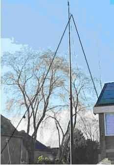
During my experiments and tests with antenna tuners on HF, I always used a thermocouple meter as an indication of the current in the feeder line. It was not intended to accurately measure the current, but to determine whether a tuner delivered more or less output. That was somewhat cumbersome because the instrument had to be placed in one wire and then in the other one. The plan existed for years to do it with a at present "classic" way: with two ringcores and two meters. The latter were purchased for that purpose at least a decade earlier.
RING CORE/TOROID
I notice that little attention is paid to the broadband nature of the applied system in published designs with ferrite or powder-iron ring cores
|
|
|
A toroidal core around a wire acts as a choke for HF current through the wire. It will be clear that the self-induction must be kept as low as possible by, for example, using a powder-iron toroidal core.
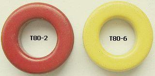
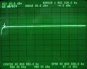
To get clarity, tests were done (fig ») with red (mix.2) and yellow (mix.6) types of Amidon or Micrometals.
It turned out that the yellow cores gave too much loss on the 160 m band. The best result was with the red type and a load of 50 Ω, see the image (fig ») of the spectrum analyzer. The line is almost straight from 1.8 to 30 MHz, with a light slope at 160 m. The -4.3 dBm ratio relates to the grid line just above it and not to the 160 m slope!
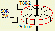
The choice was a T80-2 with 25 turns. It is suitable for greater power, wire can be fitted more easily and it fits well over a piece of RG213 coaxial cable of which only the inner conductor with insulation is used to pass through the ring core!
CIRCUITRY
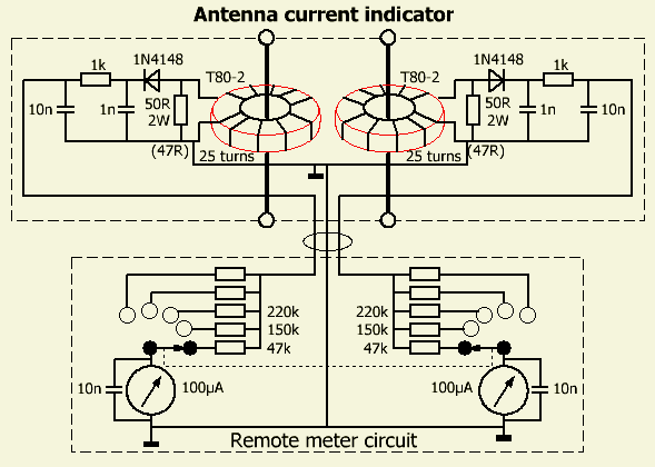
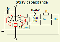
 The circuit («fig) is split into two parts to be independent of the measuring point and the arrangement of the meters. The 1 nF capacitors serve as a reservoir for the rectified signal. A large capacitance at this point works as considerable HF short circuit for the diodes and therefore possibly a too large diode current, hence the specified value. The 1 kΩ and 10 nF serve as a choke and decoupling of the measuring system and also as a protection against short-circuiting the connection to the meters.
Because here 0.6 mm of wire was in stock, 25 turns were applied.
Instead of a switch with two decks, a double tandem potentiometer is also possible. The former was chosen, because such potentiometers are rarely exactly equal to each other.
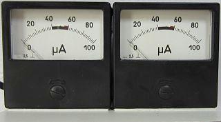
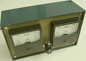
With my present antenna system and the resistors shown I can measure the antenna current up to a power of 1 kW.
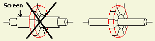
Often the screen of coaxial cable («fig) is used to reduce capacitive coupling between coil and wire of the line system. In my opinion, that actually increases the capacitance. When the screen is removed and assuming that the coiled toroid core is about 1 cm thick, it will have a capacitance of at most 1 pF with respect to the inner conductor when slid over the "bare" RG213. After all, 1 cm of RG213 has a capacitance of approximately 1 pF. In the circuit there is a maximum of 5 pF between the through wire and the rest of the circuit.
DIODES
When working with QRP power, the system can become more sensitive with germanium diodes or schottky types such as BAT85 instead of the 1N4148 shown.
A POSSIBLE CONSTRUCTION
When experimenting, I always start with a haystack circuit first. You know the a tangle of wires and components, which gradually spreads during the process by installing or dismounting. If the project works, a clearer test circuit will be built to test everything again. Then the final construction follows. Usually it doesn't go beyond the test circuit for me, because it works in practice, is good enough, or something else catches my interest.
|
|
|
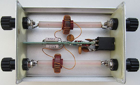 |
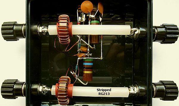
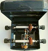
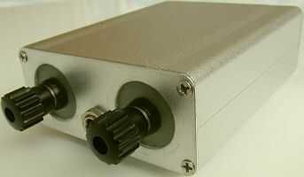
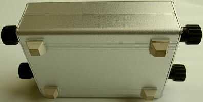
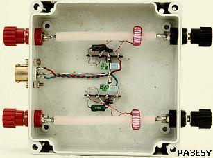
At a later stage the contents of the left plastic box were mounted in the right metal box.
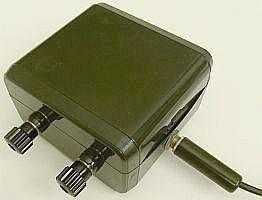
The test circuit was installed in a plastic watch box with a hinged lid. The components are self-supporting mounted on the chassis part of a stereo microphone plug. The resistors are 56 Ω instead of 50 Ω. I had them lying around and they are usually used as parasite stoppers of HF amplifiers. The lead-through of the toroidal cores is made of RG213 from which the insulation and shielding has been removed. The brown tubes are Teflon (from a broken coffee maker) to keep the toroids in place.
It is not clearly visible in the photo, but the components of both measuring systems are mounted almost symmetrically.
EQUALIZE IMBALANCE
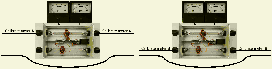 You may have noticed that both toroids are mounted differently from each other. Especially on the higher HF bands, shifting it can generate more or less current than on the other wire. Adjustment can be done as follows:
A wire is led around the outside of the measuring head and with sufficient drive on a higher HF band, read the current on meter A. For example 20 µA. Then the wire is routed through the other input and output. Now the antenna current is read on meter B. If this is other than 20 µA, it can be adjusted to that value by moving the toroidal core.
R9FF
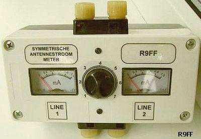
R9FF emailed me that he also built such a system. Given the text on his product, it was apparently made in response to another Dutch publication. As I mentioned before, it is slowly becoming a classic circuit.,
PA3ESY
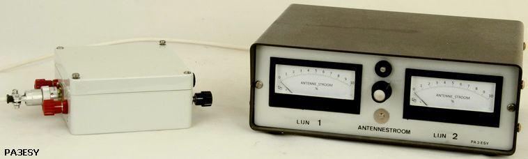
PA3ESY has also made a nice version of this meter. See his website for more details.
![]()