YAESU FT-736 MODIFICATION
![]() 26-jul-2012 With schematic version 26-jul-2012.
26-jul-2012 With schematic version 26-jul-2012.
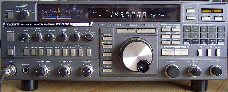
INTRODUCTION
The schematics of FT-736R's switched power supply are on Internet, apart from DL7VHF's, not clear images. In this article I paid more attention to it and some components are mounted differently.
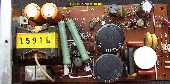
FP-1274A PSU
R11 is 4k7!
Note: the value of all components drawn in the schematic was originally installed on my PCB FP1274A-051. To be safe I removed Q4 (2SC3536) and mounted a BUV48A. Details of schematics published on Internet can be different. G8JACI replaced Q4 with a 2SC4429, which is rated at 1100 V/8 A, 60W and have the same pin configuration as the original, it works fine. These are easily available in the UK.
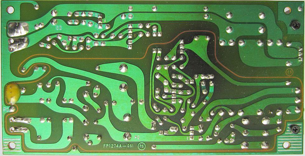
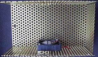
Blackened area at the track side because two 33 Ohm resistors can not get rid of their heat also because the PSU is still connected to the mains when the FT-736 is switched-off.

The PCB is blackened and two capacitors can be heated too much.
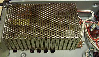
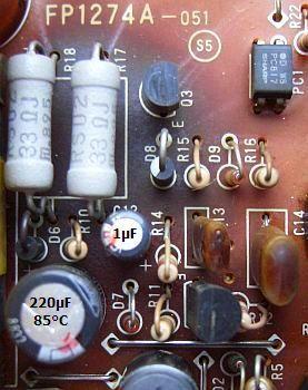
The components in question are located in the yellow-circled area. The PSU is mounted upside on the lower cabinet half of the transceiver. Two relatively small 33 Ω/2 W resistors (R17, 18) in parallel produce much heat that is "screened" by the reverse board. After a time the PCB is often slightly charred and bad solder joints occurs at the track side. The problem ultimately leads to faulty 1 µF en 220 µF electrolytic capacitors. Although my FT-736 had no problems and the soldering pads were intact, a number of safety modifications were made.
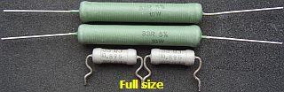
Instead of two small resistors a pair of 33 W Ω/10 types (fig») with long wire ends is used. This produces a reduced thermal conductivity onto the PCB and a better functioning of the cooling. To install the longer resistors above the PCB a jumper was removed and replaced by a "U" shaped jumper as support and contact pin.
Because the capacitors are still looked good they were not replaced.
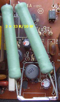
A "U" shaped jumper as support and contact pin to keep the wire wound resitors on sufficient distance of the PCB.
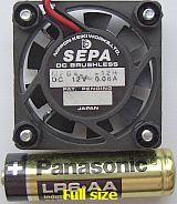
I had in my stock a small 40 × 40 × 10 mm fan that fits on the inner side of the cage just between the left orange electrolytic capacitor and the right ferrite choke. So even for the security it was installed.
To temper the fan's noise the supply voltage was reduced to about 8 Volts with 6.2 V zener diode in series to the 13.8 V plus tag on the PCB.
NOTE If the FT-736 is off the PSU is still connected with the mains and the fan is running!
LINKS
http://oz1db.dk/ft-736r/yaesuside_eng.html
http://www.xs4all.nl/~ketel/ham/ft736.htm
![]()
|
|
