EL519 & PL519 passive-grid 400W linear HF amplifier
![]() 15 Aug 2019 Update schematics.
15 Aug 2019 Update schematics.
|
Schematic in RSGB Handbook (Fig. 1) |
|
|
|
|
Published in RSGB Handbook 8th Edition: FRINEAR 400 LINEAR (RSGB's RadCom aug 1992).
A passive-grid 400 W linear HF amplifier, the PAOFRI Frinear. Screen-grid voltage is derived from the RF input and no grid bias supply is required PAOFRI's Frinear-400 is shown in the schematic. It has several interesting features.
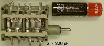
• Being a passive-grid amplifier, most of the input power is dissipated in a hefty non-inductive carbon resistor applied to the control-grid of the valve.. This type of linear has many desirable features, including low cost, low component count, stability due to the swamping effect of the passive grid input load and simplicity of the construction. Because the control grid is loaded with a resistor, the amplifier is in principle stable. Considering the low value of the resistor (50 or 68 Ohm), one might expect this arrangement to be frequency-independent; however, the capacitance of the four grids, sockets and associated wiring add up to about 100 pF which is only 55 Ohm at 29 MHz! This capacitance must be tuned out if what is adequate drive on 3.5 MHz is to produce full output on the higher-frequency bands. PAOFRI does this with a dual-resonant circuit (L3 and ganged tuning capacitors) similar to the well-known E-Z-Match antenna tuner; it covers 3.5-29 MHz without switching.
• The screen grids in this amplifier are neither at a fixed high voltage nor at earth potential but at a voltage which is proportional to the RF drive. To that end, the RF input is transformed up 3 ÷ 1 in T1, rectified in a voltage doubler and applied to the four bypassed screen grids through individual resistors. This method is consistent with good linearity.
• Control-grid bias is not taken from a mains-derived negative supply voltage but the desired effect, reducing the standing current to 20-25 mA per valve, is obtained by raising the cathodes above earth potential. The bias voltage is developed by passing each cathode current through an individual 100 Ohm resistor and the combined currents through as many forward-biased rectifier diodes as are required to achieve a total standing current of 80-100mA. The individual cathode resistors help in equalising the currents in the four valves. During non-transmit periods the third contact set (RLA3) on the antenna changeover relay opens and inserts a large (10 kOhm) resistor into the combined cathode current, which thereby is reduced to a very low value.
• The pi-filter circuit for 3.5 and 7 MHz is wound on a powdered-iron toroid which is much smaller than the usual air-core coil. This is not often seen in high-powered amplifiers due to the fear that the large circulating current might saturate the core and spoil the intermodulation performance but no distortion was discernible in a two-tone test.
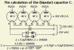
• In Fig 1, the 42 V filaments of the four valves and a capacitor are shown series connected to the 240 V mains. This 0.3 A chain is the way these valves were intended to be used in CTV sets and it does save a filament transformer, but this method is not recommended for experimental apparatus such as a home construction project. Besides, a 6µF 250 VAC capacitor is neither small nor inexpensive, and generally not available from component suppliers. Also, with lethal mains voltage in the amplifier chassis, the mains plug must be pulled every time access to the chassis is required and after the change or adjustment is made there is the waiting for filaments to heat up before applying HT again. It is much safer and more convenient to operate the filaments in parallel on a 42 V transformer (3 × 12.6 + 5 V will do), or to use EL519 valves in parallel, series-parallel or series on 6.3, 12.6 or 25.2 V respectively.
• This amplifier was stable and build without a parasitic suppressor in the tank circuit. If any instability occurs fit a suppressor.
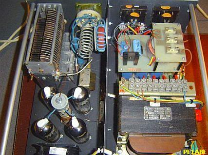
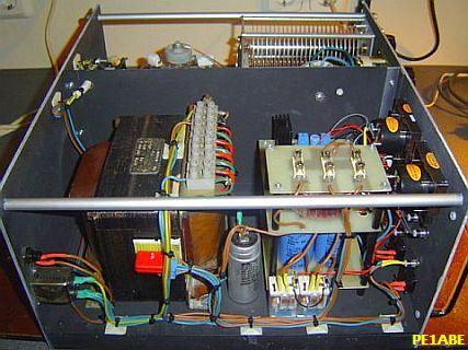
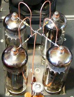
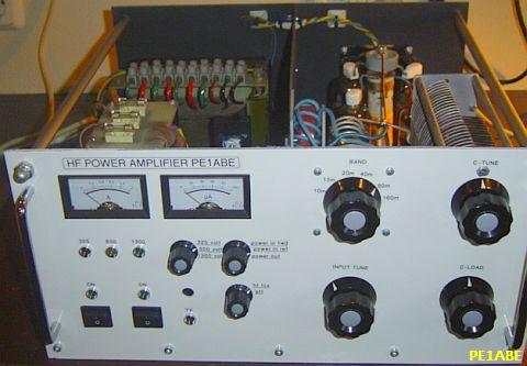
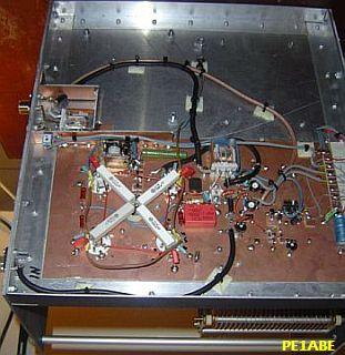
PE1ABE's home brewed amplifier.
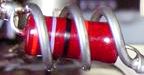
PARASITIC SUPPRESSOR
|
|
|
A method of parasitic suppression is the insertion of RF current (hairpin shaped) obstacles (dampers) at right angles («fig) to the probable flow of the parasitic currents. This method can be used up to frequencies of several 100 MHz without noticeably reducing fundamental power. The main function is to provide a high VHF/UHF impedance path in series with other (tank) circuit elements. However such method can be used only where the fundamental and parasitic frequencies are sufficiently far apart, so that excessive resistive losses of the fundamental frequencies are avoided. The circuit should have a L/C ratio al low as practicable and be sufficiently damped to achieve a broadband effect.
Damping can be achieved by paralleling the hairpin circuit inductor with a non-inductive resistor and by making the inductor from poorly conductive metal. A mat surface rather than a polished surface may provide sufficient surface resistance. The resistive component need often be no more than a nickel alloy wire/strip or tinned copper wire/strip with a DC resistive value of a fraction of one ohm. If you use 1 - 2 mm diameter tinned copper wire, it will have sufficient skin resistance for VHF. Cut off a 12 cm long piece of wire and bend it around a piece of pipe 25 mm od., solder a lug on each end.
All my amplifiers with EL/PL519 were so stable that no parasite stoppers were needed at the anode. This also depends on how such a PA is built and not everyone has experience with it. Some rebuilders of my designs were confronted with instability but that disappears after parasite stoppers were applied to each anode. On the right (fig») you can see how someone that did as a precaution. If the amplifier still appears to be unstable, increase or decrease the size of the hairpin a little.
SCREEN SUPPLY PRINCIPLE
The screen grid is neither at a fixed high voltage nor at earth potential but at a voltage with is proportional to the RF drive. To that end, voltage is derived from a small portion of the input signal, rectified in a voltage doubler applied to the bypassed screen grid. This method is consistent with good linearity. In the absence of drive there is no screen voltage and the idle current is very low. It is as if the system works as zero bias
Not everyone understand the principle of diriving screen grid voltage from the input signal. The system is often applied indiscriminately to other tubes (for example, QE08/200) without proper adjustment procedure.
This article applies the principle of Figure 2 («fig). Without drive set the idle current with a number of diodes in series. Due to anode current cathode resistor R2 provides a positive voltage which is proportional to an instantaneous screen grid voltage. The latter is derived from a small portion of the input signal and rectified in a voltage quadrupler. The cathode voltage creates a negative voltage of the control grid with respect to ground. The more drive the more the tube conducts. If R2 is too small the negative voltage reduces and screen grid current increases, so that screen grid voltage collapses. If the resistance is too large the anode current decreases and ouput drops.
 It will be clear that screen grid voltage and cathode voltage are inextricably bound up with each other and that their relationship also depends on driving power. A 100 Ohm cathode resistor is a good compromise for a 10 W exciter.
|
|
|
|
|
This design with a GU-50 (Γ?-50, FU-50S) is not tested. |
|
![]()
![]()