YAESU FL-2100Z Linear HF Amplifier Mod
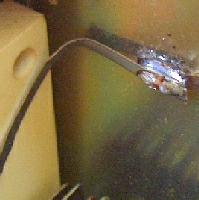
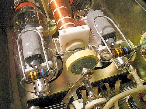
![]() 04-sep-2023 PA3HBT's GI7B conversion.
04-sep-2023 PA3HBT's GI7B conversion.
|
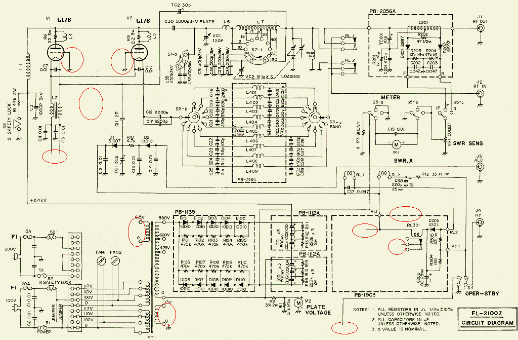
1. Rerouted variable capacitor VC1 ground path. 2. Install HV glitch resistor + fast fuse. 3. Added 4n7 bypass at HV glitch resistor. 4. Added 4n7 bypass at plate choke bypass capacitor C3. 5. Repair or mod plate choke. 6. Repair or mod parasitic suppressors. 8. Diode protection on meters. 9. Test output. 10. Some tips. |
|

YAESU FL-2100Z.
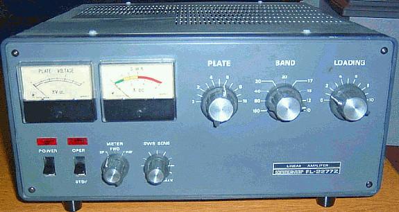
SOMMERKAMP FL-2277Z.

YAESU FL-2100B.
In the amplifiers real components were used to create a nice and compact amplifier.
-----------------------------
DB5AR MODIFICATIE
DB8AR wrote that 220 pF for C8 and C9 are too small on the lower bands 30, 40 and 80m. If this is increased to 1000 pF, the drivel goes down. Like on the 40 m band, where the modification required 80 W for 600 W output. After the change, only 45 W was needed for the same power. I haven't tested this mod myself yet.
-------------------------------------
|
Click to Enlarge. |
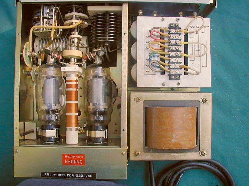
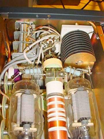
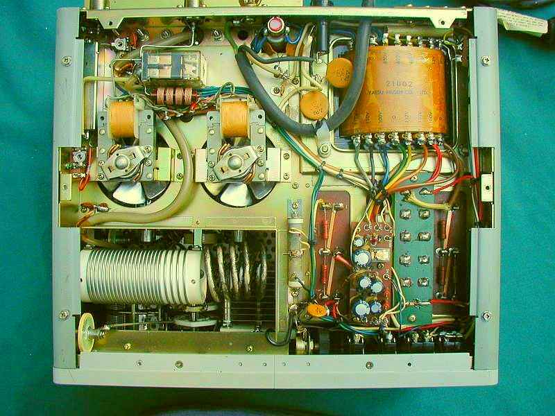
An YAESU FL-2100Z (or the equivalent SOMMERKAMP FL2277Z) is a linear amplifier for 160-80-40-30-20-10-15-12-10 m and has a separate input circuit for each band. It has two 572B/T160 tubes in an AB2 earthen grid configuration and especially designed to be used together with the FT-101ZD or FT-901DM. Two horizontal mounted fans cool the tubes. The earlier models FL-2100 and FL-2100B are largely similar but cover fewer bands.
The maximum output is not always achieved and an internal or external antenna tuner is needed in order to get everything out due to the poor SWR on some bands.
The Sommerkamp is relabelled Yaesu manufactured equipment: Internally only Yaesu components are to be found.
|
Key down (carrier) output! |
|
|
|
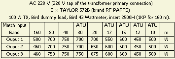
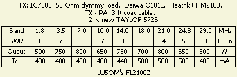
After normal tune up of the FL-2100Z, increase the power output of the transciever to full output and readjust the PLATE & LOAD for maximum RF power out of the amplifier. Your grid current (Ig) will be a little over 200 mA so make it quick! During SSB transmission after tuning like this, the Ig meter never deflects beyond 100 mA. Average Ig during SSB is what's important. Peak Ig, which your Ig meter will not read, is not important. During 20m CW tune up you see around 600 -700 W/500 mA cathode current (Ic) and 150 mA grid current (Ig). In manuals 1200 W was stated as Plate Input Power, but that is the tubes input power from the mains. Still I see it advertised in ads. Remember that the real output is about half of the input power. |
||
The input SWR and output depends on the neutralization e.g. adjusting of TC2 is my experience, see the next topic.
As expected LU5OM's experiments with the neutralization shows that transmitting power and input VSWR was affected by the setting of TC2. Tuning was according to the manual with a dip at 10 m. The output could only be achieved with an additional tuner between IC7000 and FL2100Z.
The amplifier is very stable due to the modifications in this article and eventually neutralization may even be omitted. Because the 9 fixed tuned input circuits are designed with that system it was left intact to keep the SWR modest. The neutralization method in the manual reduces the output of 10 and 12 m significantly.
|
-Tune the amplifier for maximum output on 10 m. -At full drive, adjust TC2 for minimum input SWR. -Repeat this procedure one time. |
After a few experiments with C2 the chosen trimming procedure was:
This method also shows that the lowest SWR is obtained at many bands. The stability can be checked (with a non-active exciter) by loading the amplifier into a 50 Ohm dummy load. Set the OPER/STBY switch to OPER. Close the T/R relay via J4 (= RY). Note the idle current while slowly turns the Plate and Loading knobs clock and anti clockwise. Repeat this procedure on each band. If there is no change of the idling current, your amplifier is stable enough.
There are two shortcomings: the tubes like to oscillate and there is no protection against "flash-over". The FL-2100Z is a more or less copy of the Heathkit SB-200. In the referenced article there may be useful technical information and modifications for your Yaesu amplifier.
|
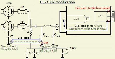
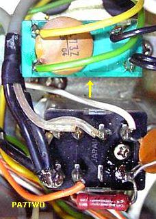
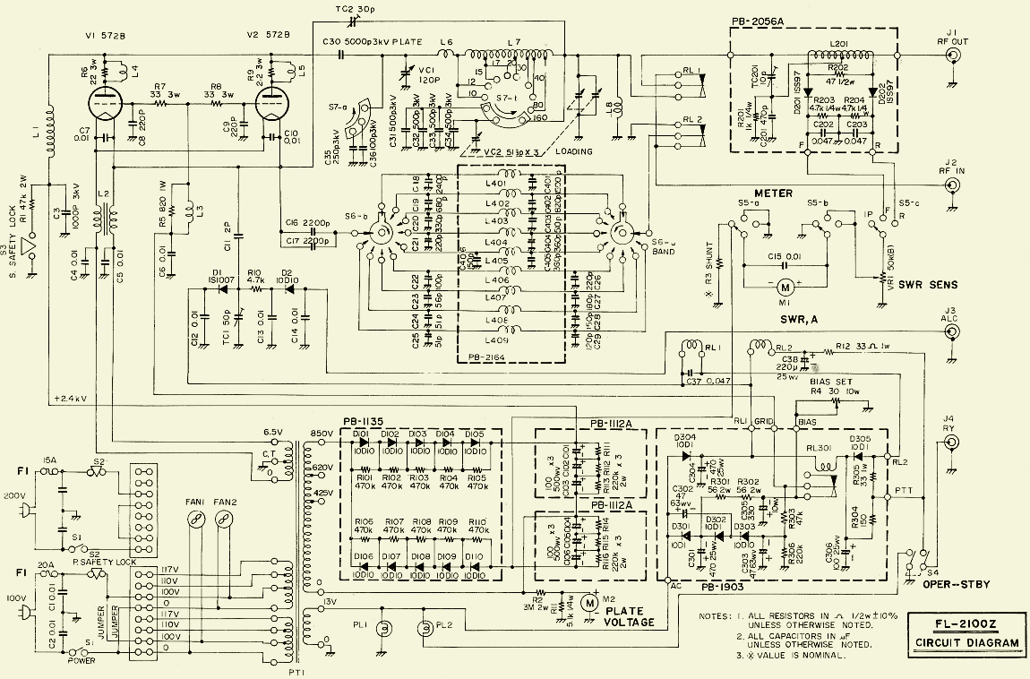
Protection circuit: 1 glitch resistor + 1 fast fuse |
|
The 572B have the nasty habit of a "flash-over" if they have not been used in a long time. The main fuse can blow and the tube can be damaged by the momentarily short in the valve if there is («fig) no fuse and resistor in the anode circuit. In addition the high voltage diodes can be destroyed which leads to the transformer demise. One of the first FL2100Z that I inspected had this fault but the valves survived because the protection circuit had been installed.
In one of the amps that I've taken care of, the contacts of the relay’s springs were out of alignment. Attempts to get the contacts right failed because the transparent lid did not fit well on top of the relay system. At first I thought it was a failure of one device, but a following FL-2100Z was manufactured with the same deviation. Check your PA at this fault!
|
|
|
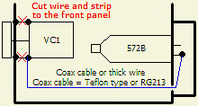
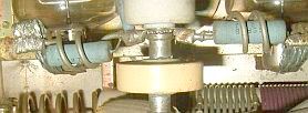
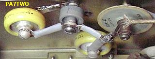
The diagram shows the circuit enhancement to prevent both deficiencies. It is best to earth VC1 to one of the valve sockets (or a common earth) with heavy wire or, even better, a piece of coax. It is shown in the diagram how the ground connection of VC1 has been shielded from the ground of the valve sockets. (This is common to a lot of amplifiers.)
A HF current from the tube via the capacitor to the tube sockets must overcome many barriers and reaches finally the sockets in the screened socket box. That caused is my belief instability and undesirable oscillations. A shorter solid direct connection forces the HF current from VC1 in one direction straight to the tubes.
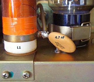
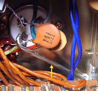
A resistor and a fuse in series with the anode connection give protection against "flash over" and a short. Add two 4.7 nF capacitors to improve the decoupling of L1 («fig) on 80 and 160 meters.
|
|
|
|
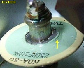
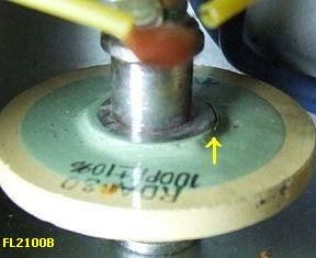
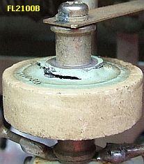
The best is to cut the short wires at the top and bottom VC1 so that HF current only can flow through the new wire or (fig») coax cable.


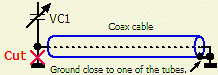
VC1 to tube socket with heavy (6mm²) wire (left) and coaxcable (center).
The pictures show the short way to implement these changes. Drill a hole in the socket compartment and possibly mount a grommet. Subsequently use some 6 mm² wire (or RG213 etc.) from the bottom of VC1 to one valve socket. Insert some protection against the wire touching the chassis or ensure that the wire does not touch the chassis anywhere else.

Rerouted VC1 ground path to tube socket with RG213 coax cable.
VC1 to tube socket with heavy a 6 mm² wire.
VC1 to tube socket with heavy a 6 mm² wire.
See («fig») a wire or coax cable grounded at one point (tube socket or chassis).
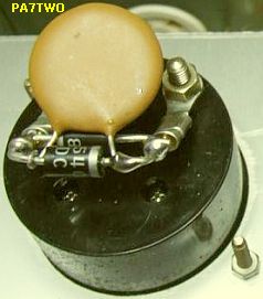
PA7TWO made first the modification with two wires to both valve sockets. However he kept on having parasitic oscillations. He tried almost everything until finally in desperation used only one wire from VC1 to one valve socket. Then, to his great relief, the amplifier became very stabile and both tubes had the same healthy red shine by long continuous transmissions. PA7TWO’s experience once again shows that it is important to select (as I advised in my other PA articles) a single connection point, common to both valves, as close as possible to the valve sockets. The other end is only connected to the tuning capacitor.
|
|
|
|
|
|
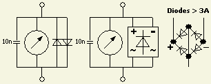
If something in the HT supply goes wrong then meters may be damaged. Often no replacement is available. Suggested is to protect all panel meters with back-to-back connected diodes. Bridge rectifiers are very suitable too. In addition decouple with some 10 – 22nF capacitors because modern high voltage diodes can work well into the HF region. |
|
Hans PA3HGT and Henk PA0HRA have applied the modifications in their FL2100Z. Hans has an extensive guideline with many pictures on his homepage: http://www.pa3hgt.nl. look for "TechShit".
It is recommended to apply these modifications to other manufacturer’s amplifiers. Almost every linear amplifier that I get leaves with the same protections.
|
This (fig») happens with the S3 SAFETY LOCK if you apply HT without the top cover. |
|
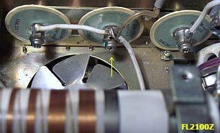
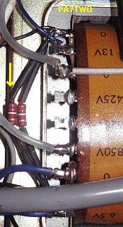
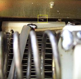
The air pressure of the two fans is minimal and creates an airflow that is hardly noticeable. During long transmission period's e.g. during a contest, slow scan TV, RTTY etc. the area with the tubes gets pretty hot. Often this results in damage to the doorknob capacitors that will crack or short through overheating.

|
|
|
The air pressure of the two fans is minimal and creates an airflow that is hardly noticeable. During long transmission period's e.g. during a contest, slow scan TV, RTTY etc. the area with the tubes gets pretty hot.
That explains the common problem of failed ceramic disc capacitors next to the tubes. They crack or break by overheating shortcut is also commonplace. Links you can see how a defective copies PA7TWO has replaced by more modern types. On the left shows how PA7TWO has replaced faulty capacitors by more modern types.
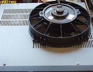
An extra ventilator can be placed on top of the cabinet to improve cooling and extending the life of the tube. A near new radiator fan for a VW («fig) was bought at a car wrecker by PA7TWO. At 5 VDC this runs very silent while at the same time the airflow is "out of this world".
Another option is to use some 12 V/ 2.5 W fans as used in computers. The filament supply is sufficient to supply the fans too. Make sure to make this DC "floating" (fig») without a connection to earth!
This linear was produced to complement valve transceivers. With the modern semiconductor transceivers this results in problems due to the fluctuating SWR. An external or internal tuner is required to drive the linear properly with sufficient power.
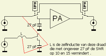
The thin hook-up wire and long connections to the relays in the input circuit creates problems, especially at the higher HF bands. A 27 pF capacitor across the relays contacts (sometimes even across the input connector) creates a broadband tuning of the cabling in the 10 – 15m frequencies. Using a trimmer can improve results even more. Wiring using coax cable can help but often the capacitor is required due to the cabling around the relays.
PARASITIC SUPPRESSION CIRCUITS
A method of parasitic suppression is the insertion of RF current (hairpin shaped) obstacles (dampers) at right angles to the probable flow of the parasitic currents. This method can be used up to frequencies of several 100 MHz without noticeably reducing fundamental power. The main function is to provide a high impedance path in series with other (tank) circuit elements. However such method can be used only where the fundamental and parasitic frequencies are sufficiently far apart, so that excessive resistive losses of the fundamental frequencies are avoided.
The circuit should have a L/C ratio as low as practicable and be suitably damped to give a broadband effect.
Damping can be achieved by paralleling the hairpin circuit inductor with a non-inductive resistor and by making the inductor from resistive material. A mat surface rather than a polished surface may provide sufficient surface resistance. The resistive component needs often be no more than a nickel alloy wire/strip or tinned copper wire/strip with a DC resistive valued of a fraction of an ohm.
|
|
|
|
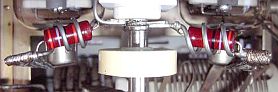
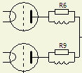
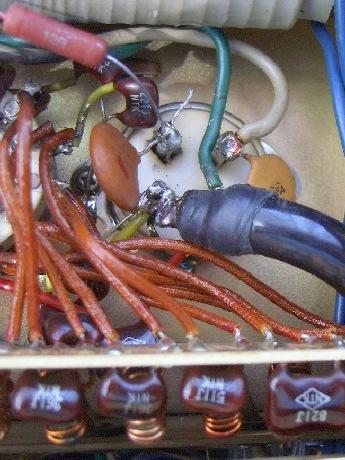
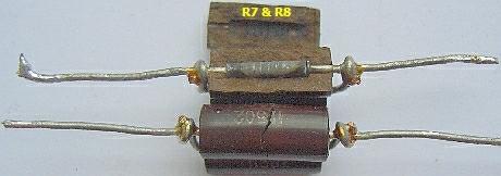
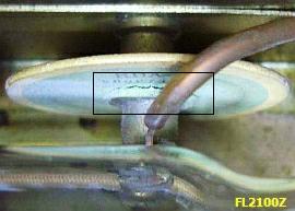
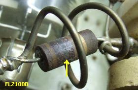
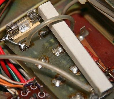
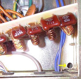
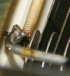
The suppressors in this amplifier are small coils L4 and L5 respective paralleled with R6 and R9. They prevent parasitic oscillations in the VHF region. The value of a resistor is not critical (22 -100 Ohm) but it needs to be non-inductive and has the purpose to broadband for VHF.
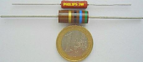

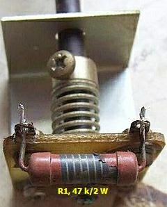
A blackened resistor needs to be replaced. The vintage (fig») non-inductive carbon composition resistor is no longer manufactured and hard to find and a modern equivalent are 3 W brown Philips in values from 22 to 470 Ohm. Most shops have («fig) the smaller 1.2 W version in stock. Make sure to ask for the 3 W ones. Mount the resistor next to the coil, not inside it. Eventually mont 4 × 220 Ohm/1.2 W in parallel.

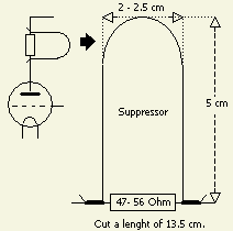
If you happen to have to replace the coil make then a hairpin according to the diagram and picture. A standard "design" was developed after much trial and error and consists of 12 cm wire shaped in a "U" with a distance of 2 cm between the "legs". However use 13.5 cm and use the 1.5 cm to wind around the legs of the resistor and solder it. Use standard tinned wire because this introduces additional losses on VHF ensuring a broadband functioning of the trap.
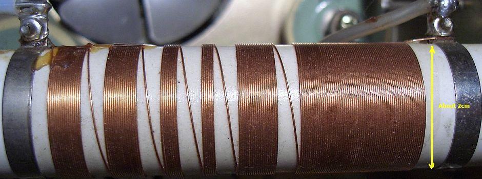
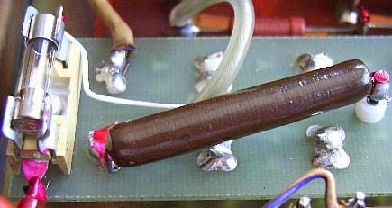
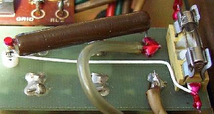
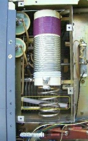
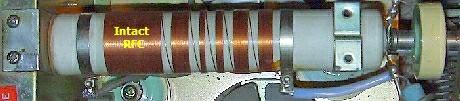
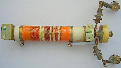
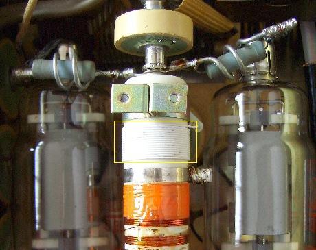
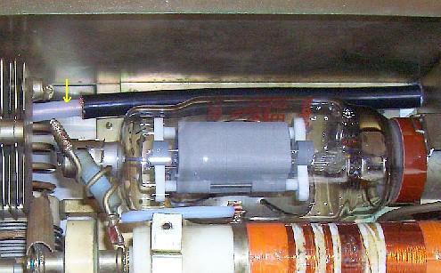
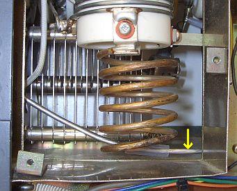
Info for homebrewers: RFC L1; the turns per section. 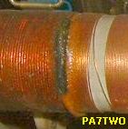
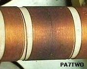
The photograph of the anode RF choke (L1) is shown that the number of windings per section may be counted in the event that you are dealing with a burnt or burnt coil. Possibly you may fix the coil.
|
|
|
A defect tube can have various causes such as the absence of the previously described security, tuning to the wrong band or working without a load. An amplifier was investigated and showed a repaired choke, apparently the RFC also burned due to a defect tube. To restore the previous owner had removed the damaged windings, a section rewound and then the loose ends soldered together. The coil becomes a false resonance in the 12 m segment making it virtually impossible to obtain some output on that band. By applying additional windings of thin (Teflon) insulated wire, I shifted resonance and the output on the 12 m band increased to the usual value.
|
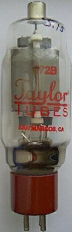
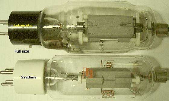
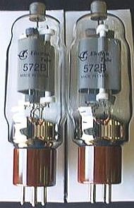
Full size Cetron 572B and the smaller Svetlana's type. |
Several reports point out that the Svetlana tubes with their higher µ are not very suitable for HF. Apparently these were designed for LF amplifiers. On the photo you can see that the anode is considerable smaller in size than another manufacturer’s "normal" 572B. The anode dissipation of the Svetlana is subsequently smaller.
The valve shown in the picture was totally "worn out" (perhaps through misuse?) and more power went in than came out. If you look carefully then you’ll see that the valve is shorter than those of other manufacturers are and modification of the amplifier may be necessary to connect it.
|
|
|
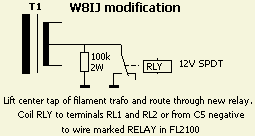
With tubes that have a higher µ that the original 572B the negative bias to "close the tube" may be too low. If the amplifier is not loaded properly this may result in self-oscillation of the amplifier. W8IJ uses a 100 K resistor to the centre of the filament winding to prevent this. A relay shorts this resistor to earth when transmitting. PA7TWO has applied this modification with success.
Often matched tubes are recommended and this goes hand in hand with a substantial increase in price. Although there may be a place for this in some amplifiers in this amplifier and Heathkit SB-200, Ten Tec Centaur or Ameritron it is not required. I have about 15 × 572B and 13 are from different manufacturers. These have been in mixed usage in my amplifiers in 2 × 572B and 3 × 572B set-ups without detecting anything detrimental.
In the schematic both tubes are equally driven, but due to the assembling of the components will always be a difference between the two tubes. In my opinion matched (real) transmitting tubes does not make sense. The HF current chooses the shortest route and therefore has a preference for one of the two tubes. If one anode is redder than the other is changing the tubes can compensate the difference.
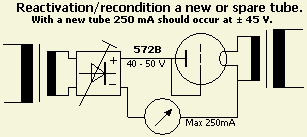
To avoid flashover in a new or a long time unused tube, it is prudent to prepare ("reactivate") it for his task. There are various opinions and solutions how to do it, but with a 572B it can be relatively simple. A DC of 40 to 50 V is sufficient for the tube to draw 250 mA as the grid is connected to the anode. Heat the tube 30 minutes with a filament voltage of 6.3 V. Then supply a "high voltage" of about 45 V and set the voltage to a current of 250 mA. With a new 572B a current of 250 mA should occur at 44 - 45 V. If possible use a current limiter, because during reactivate the current can increase suddenly so that continue monitoring could be necessary to maintain 400 mA. Usually I will not reactivate longer than an hour. Soon you will find out at which voltage a good tube drawn 250 mA, so you have an indication if another tube is better or not.
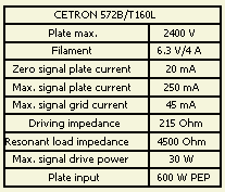
All good used or new TAYLOR, WATERS and CETRON tubes that I could test were remarkably similar, as they were 250 mA at 44 Volts.
CHEAP TUBES
PA7TWO bought a few Chinese branded 572B’s in the US. In his Yaesu FL-2100 they perform like a charm. When he showed them to me they look like a copy of the CETRON 572B’s and when tested in my amplifier no differences with other brands could be detected.
DK6NI: "Nochmals besten Dank für Deine guten Ratschläge. http://stores.ebay.co.uk/Tubesonix
Die neuen Röhren von Tubesonix sind eingetroffen! Die SB-200 arbeitet nun offensichtlich einwandfrei".
At present the link does not work!
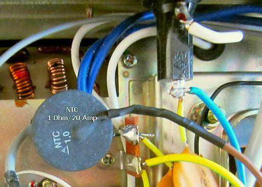 |
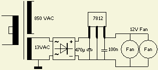
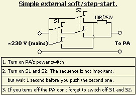
A simple but effective delay can be done with an NTC resistor. The primary winding of the transformer is only a few Ohm, so that a 1Ohm/20A NTC is sufficient to limit the large momentary switching currents of uncharged HV elco's and cold filaments. |
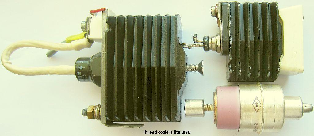
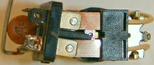
GI7Bs have the same thread as the illustrated coolers. They are narrower than the original cooler and fit alongside anode choke. Due to the construction, the tube receives a suitable transverse cooling of the underlying fans.
.jpg)
.jpg)
.jpg)
.jpg)
.jpg)
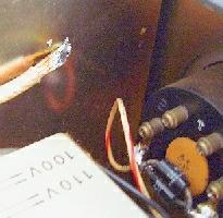
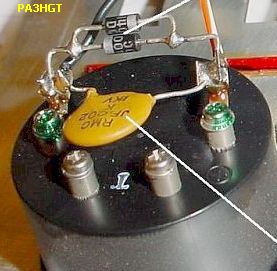
PA3HBT came into possession of a partially decommissioned FL2100 without 527Bs, but with two sets of GI7Bs. You can see the conversion in the images shown.
In his opinion was the wire of the 12 V connection of the power transformer too thin to feed the filaments of the GI7Bs. That is why he installed a small toroidal transformer between the capacitors of the HV power supply.
To sufficiently cool the tubes, three other fans were mounted. The third at the back through an additional opening.
The drive is directly to the cathode/filament, so without an input circuit. The SWR at 80 m is on the high side but decreases favorably as a higher band is used.
Output of more than 700 W is possible, but that will be a considerable overload of the power transformer.
![]()
![]()