ME-165/G SWR-POWER METER 1.8–30 MHz
With internal dummy load, Watt-meter and quiet-tuning facility
![]() 27 jan 2013 With updated schematic and added text.
27 jan 2013 With updated schematic and added text.
SWR-POWER METER ME-165/G
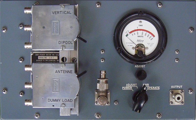
The ME-165/G is manufactured by Barker & Williamson, Inc. (SWR-POWER METER ME-165/G, Radalab (STANDING WAVE RATIO-POWER METER ME165/G) and others as matching unit designed for use with T-368 400 W transmitter. This combination dummy load/SWR/power meter is an especially useful accessory to have for a ham.
|
|
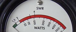
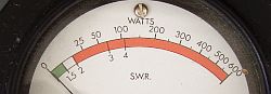
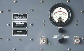
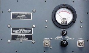
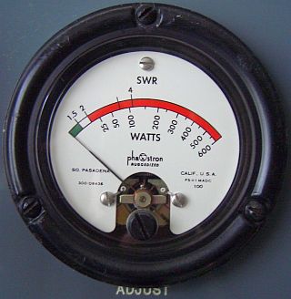
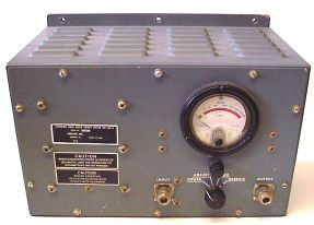
Left: BARKER & WILLIAMSON's ME-165/G, right: RADALAB's ME165/G |
The meters show something different and at Radalab's front the text is printed and at B & W's is grooved and filled with paint.
ME-165/G
|
|
|
|
|
The matching unit is provided with: |
1. Internal dummy load 50 Ω/600 W 2. Power-meter ≤ 600 W |
3. SWR-meter 4. Quiet tuning facility |
This schematic was drawn with my ME-165G PCB as an example because the original diagram was not in my possession.
Later ON4FVQ emailed a copy of U.S. ARMY Technical Manual TM 11-6625-333-15 March 1971 that contained the showed schematic.
The 1N69A diodes and the numbering of the components are different than on my PCB board, but in the "military" diagram it is shown in brackets.
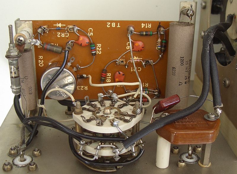
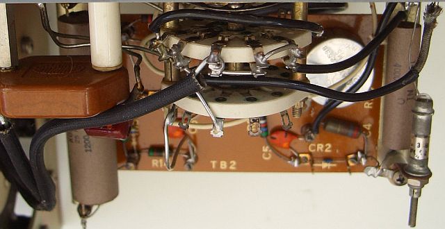
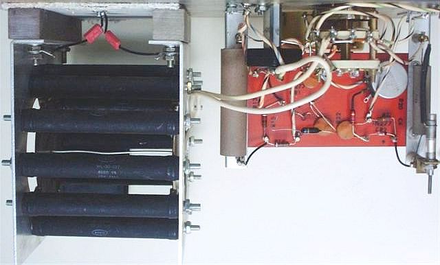
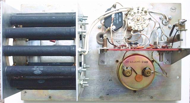
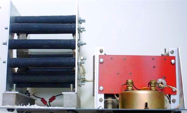
Wiring detail ME-165/G
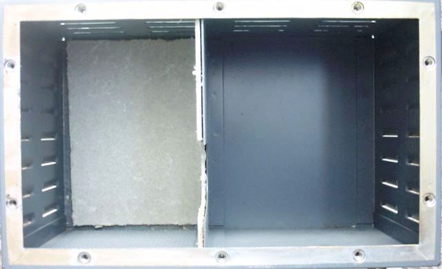
DUMMY-LOAD 50 Ω
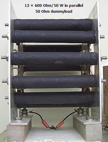
The dummy load (fig») used 12 × 600 Ω/50 W non-inductive 5% resistors in parallel to provide a 50 Ω/600 W load with a SWR of 1.5 or less up to 30 MHz. However when dissipating power in excess of 250 W limit the operation to intermitting on-off periods. Do not apply 600 W power for longer than 10 minutes. The matching unit can be damaged by the great amount of heat generated. For longer periods a ducted airflow should be used for the dummy load.
Stray inductances are tuned out with three capacitors at the input and at the ends of the paralleled resistors.
PRINCIPLE OF QUIET TUNING
In a quiet tuning system («fig) the full power is dissipated in a non-inductive resistor and a minor part of the power is used for a bridge circuit that permits direct readings of the SWR between the transmitter and its load (Antenna or tuning unit). If one is matching his ATU or antenna the low power output will not be noticed by another ham. With the control switch in the SWR position the ME-165/G's output is only 50–100 mW and the transmitter is loaded with a perfect 50 Ω match. 1N277 can replace a defect diode.
Note In my unit were CR1 and CR2 defective or not in order. In the absence of original components I replaced CR1 by a germanium diode and CR2 by a 1N4148. With the last I obtained a pretty good accurate Wattmeter scale.
After years the SWR meter readings becomes unstable. After a survey of about two days, the cause was detected in the meter. The terminals operate as diodes by oxidation. After cleaning for security C8 was replaced with a 10 nF capacitor. During the research I had already replaced C6 and C7 with 10 nF.
As an experiment germanium diode CR1 was removed and a Schottky BAT85 installed. A sensitive measurement occurs with a more accurate SWR = 1 as result. It will be clear that the device is not removed!
MATCHING SEQUENCE FOR LOW SWR
Two switches added.
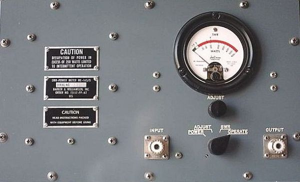
Set the ME-165/G function switch to POWER. Adjust the transmitter for cw operation. Connects transmitting power to the unit and power output is indicated on the meter.
Set the switch to the ADJUST position and rotate the ADJUST control to obtain a full-scale meter reading. Do not keep the switch in that position any longer than necessary for meter adjustment.
Set the switch to the SWR position. The SWR between the transmitter and ATU or antenna may now be read and you may match your ATU for lowest SWR.
Finally set the switch to the OPERATE position and the transmitter output is connected directly to the load.
LINEARITY ADJUSTMENT
Adjustment is best done with a borrowed accurate in-line Wattmeter.
-Set the ME-165/G functions switch to POWER.
-Adjust the transmitter for CW operation at 1.8 MHz.
-Key the transmitter and compare the power indication on the ME-165/G with the power indication on the Wattmeter so that the indications should agree within 5%.
-If the ME-165/G power meter indication is not correct within 5%, adjust ME-165/G potentiometer R17 (R23) so that the power meter indicates the same power as the Wattmeter.
-Adjust the transmitter for CW operation at 28 MHz. Key the transmitter and compare the power indication on the ME-165/g with the power indication on the Wattmeter; the indications should agree within 5%.
-If the ME-165/G power meter indication is not correct within 5 percent, adjust ME-65/G capacitor C3 (C4) so that the power meter indicates the same power as the Wattmeter.
-Repeat the procedures given above, as necessary, until the ME-165/G power meter indications are correct at both ends of the frequency range.
ACCURACY
The ME-165/G must be recalibrate with R17 (R23) and C3 (C4) after any repairs or adjustments. If the power meter is well calibrated the accuracy of the scale is almost 5% that is better than most ham's SWR/PWR meters.
Calibration checks should be done with the front panel firmly pushed to the enclosure.
The SWR reading may not accurate due to the messy wiring from input to switch, from switch to dummy load and from switch to output. Replace the messy wiring by 50 Ω coax cable.
The null on 10 m can be improved when the two wires from switch to dummy load are bound together with tie-rap cable ties or plastic and waxed-linen lacing cords.
Click to Enlarge
![]()