A LIMITING RF SPEECH PROCESSOR
A simple system based on double-sideband limiting and selection with one filter.
Experiments and a simple working design.
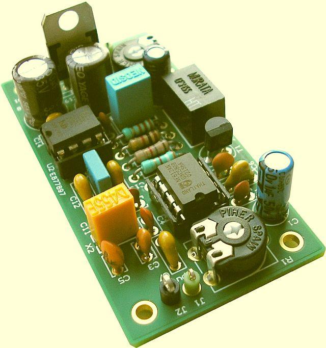
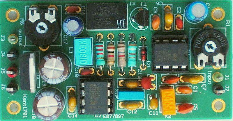
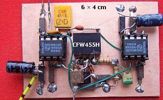
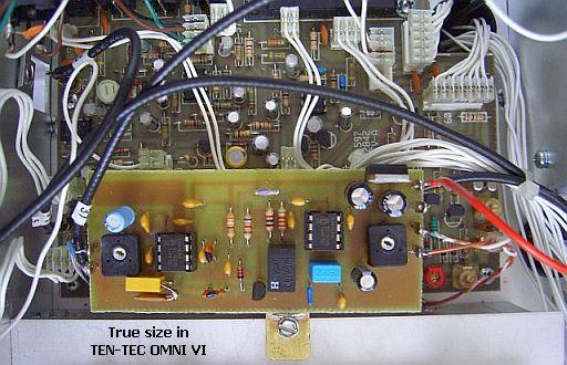
![]() 27 jan 2017: New PCB [18 jul 2011: 2 Photo's.]
27 jan 2017: New PCB [18 jul 2011: 2 Photo's.]
Rinus the owner of KENT-Electronics is SK
This PCB (printboard) designed by PAØMBJ is on request available by him: PA0MBJ@veron.nl.
 |
 |
The design can be ordered as a kit from van Dijken Electronics:
https://www.vandijkenelektronica.eu/nl/search?controller=search&orderby=position&orderway=desc&search_query=pa0fri
INTRODUCTION
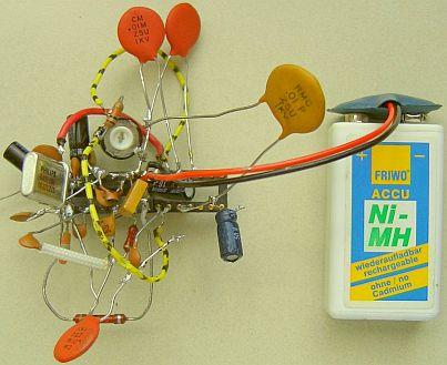
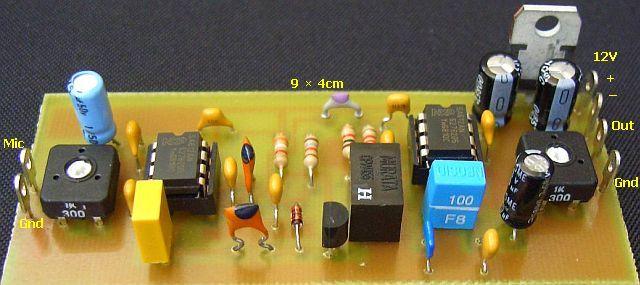
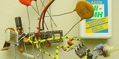
The DSB limiter in my original article (see at the bottom) gave problems for some foreign home brewers. Probably by using a different type of IC (eg TBA120S, TBA120AS, TBA120T, TBA120U) than the previous model (TBA120, TBA120A) which was used in my circuit. Moreover, the older types are difficult to obtain. Reason why I started experimenting with readily available mixer NE612A (or SA12AN). This experimental version («fig) of a speech clipper, one of the many tested designs, worked satisfactorily. See also Atlas speech processor.
DESIGN
 The double sideband signal from the first NE612A (pins 4, 5) is too weak to be limited with two silicon or Schottky diodes without idling current. During experimenting arose a clipper circuit with a diode and the emitter-base junction of a transistor (T1) as second diode. The 1k8 and 3k9 resistors are used for the best possible symmetrical clipping. Eventually can be replaced by a 5k0 potentiometer and 1K0 resistor to refine symmetrical clipping. The transistor contributes the necessary amplification for the ceramic filter CFW455H. This 455 kHz type must be loaded at input and output with 2k0 impedance, which I did at first. However no marked difference was noted with the higher values in the diagram.
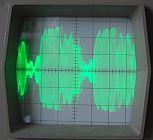
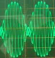
The intention is that the diodes clips and not the second mixer. With sufficient signal from the filter, the second mixer limits rather than the diodes. Therefore the filter is loaded with a voltage divider (2k2, 1K0). This («fig) can be seen on an oscilloscope with aaahhh ... into the mic.

Note that, unlike the designs of others, oscillator and RF signals are respectively routed to pins 1 and 6 of the second NE612A. I did this for more LF output at pin 4. The clipping level is determined by the strength of the microphone signal. Extreme limiting must be avoid to maintain a good understanding. Optimal is a higher average power output while the listener does not notice that a speech processor is in action. The S meter moves much less.
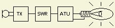
The increased average output is noticeable. Use (fig») a 230 V/100 W lamp as transmitter load and tune with an ATU for SWR = 1. Speak into the microphone without processor and then enabled clipper, see the lamp show's more light.
FILTER
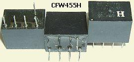
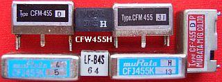
The Murata 6 kHz/6 dB, 18 kHz/50 dB CFW455H filter («fig) is selected as a compromise between bandwidth and price. The type is obsolete, but is still available via internet (ebay.de, ebay.co.uk). More modern versions with the same specifications and with the addition of "H" (eg CFWLA455KHFA-B0) are also suitable. Alternatively, an expensive and narrow SSB filter type CFJ455K13 may used.
RESONATOR
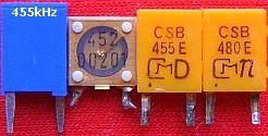
A (fig ») 455 kHz ceramic resonator is used for the oscillator circuit. Unfortunately, they seldom resonate at the specified frequency.
|
|
|
Experimentation is often needed even with items of the same type and brand. I chose for a Murata CSB455E, this model is more in circulation.
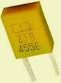
Some vendors offer («fig) a ZTB455E resonator, probably a newer version of the CSB455E type.
Experiment with the capacitance in series with the resonator for optimum modulation. For example use first a 470 pF variable capacitor.
Depending on the resonator's oscillation frequency the filter's output signal is SSB with suppressed opposite sideband or partly suppressed opposite sideband. Almost perfect SSB is obtained if the carrier is set to 452 or 457 kHz, which favour to the last frequency. Unfortunately the CSB455E does not oscillate on 457 kHz in this design. If the resonator doesn't start try (fig») the transistor oscillator of the next designs (C = 3n3 - 5n6).
OTHER DESIGNS
Both are experimental!
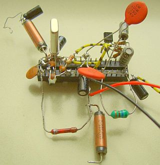
For your information here are a few of my other and possibly interesting designs. At left a compressor where T2 is used as voltage-actuated device and thereby regulates the gain of first NE612A. At right a clipper system with a third NE612A as limiter. Both systems work, but because the previous simple version performs, these circuits are not (yet) "polished".
The original article
A Double-Sideband Limiting RF (HF) Speech Processor
A simple system based on double-sideband limiting without RF filters.
SPEECH PROCESSOR
An audio or RF speech processor will give your SSB signal valuable extra "punch". An audio clipper simply either compresses or clips (or both) the audio signal. This actually ends up making your speech less intelligible, because it produces in-band distortion products. If you clip a signal, it creates harmonics, put simply 800 Hz » 1600 Hz, 2400 Hz and so on. This can (and often does) result in 'whiskers' or splatter which make the transmitted signal wider.
# Converts audio signal into dsb signal, clips & processes it for greater average envelope power
# Converts signal back into audio
# Adjustable levels of processing & output,
RF speech processing avoids this issue by converting the audio to a double-sideband (DSB) RF signal before clipping or compression. Any distortion produced will be harmonics of the RF frequency used. If the RF processor uses 6.4 MHz then the harmonics would be 12.8 MHz, 19.2 MHz etc., which are easily filtered out using a narrow band filter. The RF is then demodulated back to audio again. This gives a cleaner sounding signal for the same amount of compression or clipping and a 6 dB improvement (one S-unit) in RF SSB output power is possible.
|
|
|
|
Testing designs with NE612A, CA3028A and TBA120A. |
|
An SSB clipping processor is ideal, although somewhat expensive and complex. A double-sideband limiting processor was constructed and evaluated against an SSB-Clipper. Experimental evidence showed that the DSB-Limiting scheme performed as well as the SSB-Clipping processor when the clipping level was not excessive.
|
Saving RF filters with this kiss speech processor. |
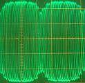
Two tone output pin 8 TBA120. Left: linear, right: symmetrical clipped. |
Double-Sideband RF Speech Processor
|
|
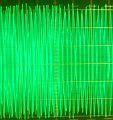
Output tx: with aahhh… into the microphone. |
This Double-Sideband RF Speech Processor takes the audio from the microphone and converts it in a NE612A to an internal 6.4 MHz DSB signal. The signal is then clipped in a TBA120A and is further converted back to audio for input to a transmitter or transceiver. The resulting harmonics (of 6.4 MHz) are filtered out with simple RC filtering when it was demodulated back to audio. The result is a 'cleaner' clipped signal being finally transmitted. This increases the average output level of an audio signal from a microphone by clipping off the excessive signal peaks. By lowering the peaks in proportion to the average level, a higher average output level can be attained with an associated increase in intelligibility under difficult conditions. It is set up easily without special equipment because no RF filters are used. It can be used with any make of rig, requiring only signal connections to and from the normal microphone socket. This effective design offers microphone level input and output adjustments. The clip level depends on the amount of microphone gain.
The ALC meter indication may not be quite as high as when the processor is off. This is normal, as the average power output is higher with the processor, although the peaks are being clipped of the loud or hard sounds to eliminate overdrive that leads to spurious and harmonics. It is possible to set the controls so that the peak envelope power reaches the desired level without activating the ALC at all.
The level then is only a few tenths of a dB below the level that would have been set by the ALC, but the transmission is a lot cleaner while maintaining very high average modulation.
CIRCUIT IDEAS
|
Eventual a tuned circuit. |
With audio band pass filter. |
|||
|
Audio band pass filter. |
Balance input for the NE612A. |
|||
These 2 circuits are not fully tested.
![]()
![]()