4 m COAXIAL J-POLE, SLEEVE, SPERRTOPF ANTENNA

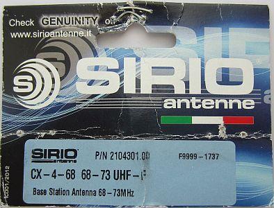
SIRIO CX 4-68
4 m COAXIAL J-POLE, SLEEVE, SPERRTOPF ANTENNA
![]() 24-jul-2022
24-jul-2022
INTRODUCTION
I made for many years a lot of antennas and the necessary "hardware" such as aluminum tube purchased from local suppliers. But since they have been swallowed or drived off by Formido, Praxis and Karwei, it is becoming increasingly difficult to find suitable metalwork from the latters. Recently, only 1 m Alu tube was available at the Praxis because longer ones were no longer in the range. Annoying if you need for example 1.25 m long pipes.
You are therefore dependent on external suppliers by collecting or sending via a delivery service.
A quick calculation showed that if you want to make a reliable antenna, the purchase and delivery costs are close to the selling price of some ready-made antennas! After comparing various antennas for 4m and reading the reviews, it was decided to purchase a Sirio CX 4-68 for 4m. Delivery costs inclusive insurance and VAT was only € 7.99.
A good opportunity to test this antenna because some reviewers stated "it is a great performer", while others complain about being filled with water after some time.
70 MHz/4 m
For local QSO's on 70,450 MHz, a home-made vertical dipole with gamma match is used. The antenna hangs in the attic on the ridge close to a side window and is sufficient for a few nearby stations.
The purchased antenna will initially be tested at the same point. Later it is installed on a 12 m high mast to replace a Cushcraft R5 5-band vertical antenna.
CX 4-68
The manufacturer calls the CX 4-68 a "3/4 λ coaxial J-pole". Truly it is not a 3/4 λ antenna but a ½ wave antenna with a ¼ wave matching stub so that the total length is approximately 3/4 wave long. Given the construction, it is in fact a coaxial J-pole, sleeve, Sperrtopf or a (Dutch "fietspomp antenne") hand bicycle pump antenna.
Due to the ¼ wave matching system with a high Q factor, such antenna has a narrower bandwidth than a conventional dipole, but that is no problem with the allocated narrow band on 4 m.
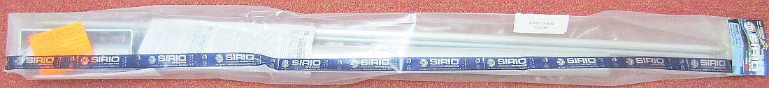
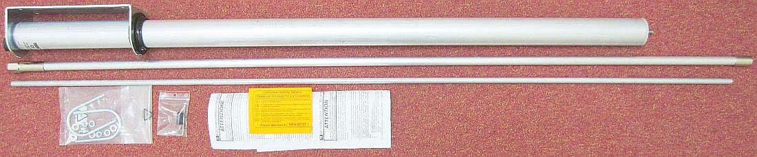
Ready made and everything complete!
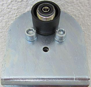
At first impression it looks solid and complete. The rubber(?) bush around the SO239 antennasocket is not attached to the bottom plate.
Water can seep past the PL259 through the space or gap between ring and bottom plate. If the coax cable is not properly installed in the PL259, water may also drip into the cable. These include the downsides that people have experienced.
Wrapping SO239 and PL259 with self-amalgamating tape may cure the problem.
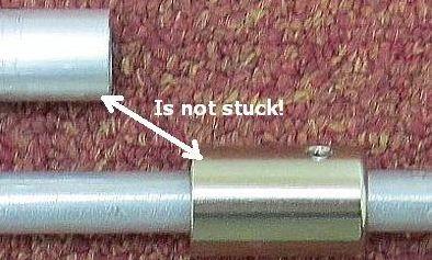
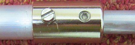
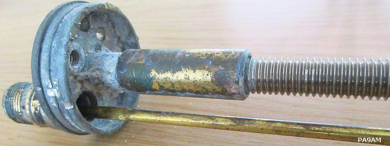
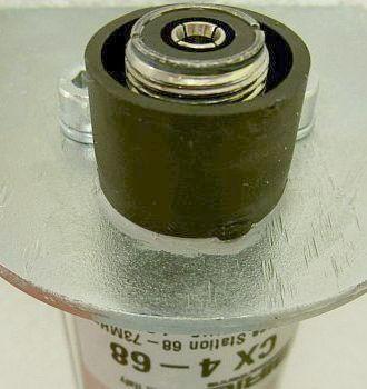
The coupler for the top element («fig) with the lower part is loose. That is why a 3 mm thread was tapped into the brass element for a stainless steel screw so that coupler and lower element are secured. It is also possible to assemble directly with a stainless steel parker.
For safety it was later extra secured with kit.
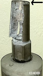
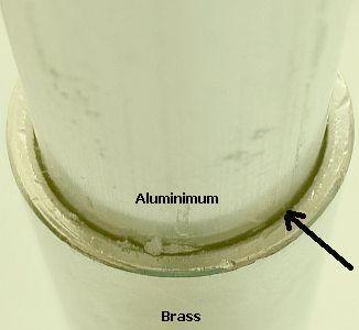
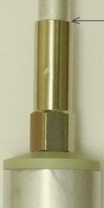
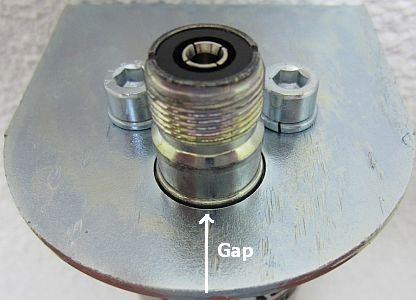
Another point of leakage and electrolysis or oxidation is the connection of the brass coupler installed at the bottom of the middle aluminum antenna rod. Acid-containing rainwater collects in the (clearly visible fig») gap, causing a chemical reaction between brass and aluminimum. The result of the damage can be seen on the image of EI4DIB («fig).
It is therefore important to seal the gap with wrapped self-amalgamating tape or by applying suitable kit such as Bison's Polymax.
GAMMA MATCH
PA9AM's flooded CX4-68.
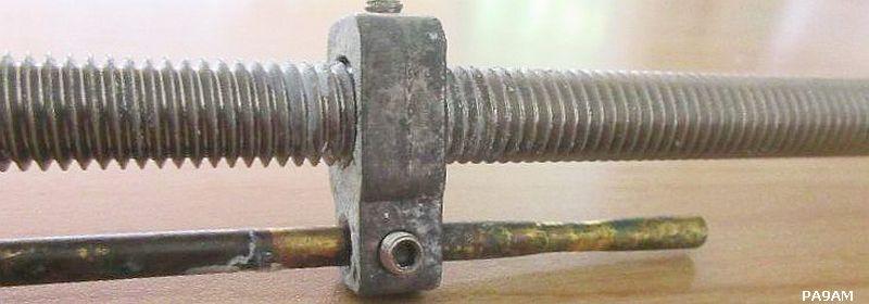
PAØFRI's gamma match system of a 2m antenna.
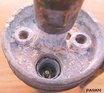
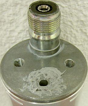
The damage caused when the antenna is "flooded" can be seen in PA9AM's dismantled CX4-68. Because he was curious about the inside, the device was cut open, which gives us a clear picture how the manufacturer made his smart gamma match.
@I also used the same principle gamma match for my home-made sleeve (fietspomp) antennas.@
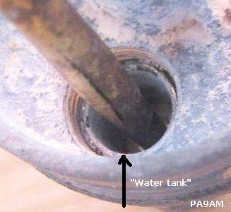
When filling up with water and insufficient drainage, water collects in the opening where the gamma match is connected to the SO239 connector. In fact, it will be a water tank with all its consequences. It would have been better if the manufacturer had filled the hole with a suitable filler.
RESONANCE
Adjustment can be done by sliding the top part of the antenna in or out and then fixing it with the socket screw.
Such sleeve antenna is sensitive to conductive metal objects in its immediate environment. Complete adjustment preferably at least 4 m from mentioned objects.
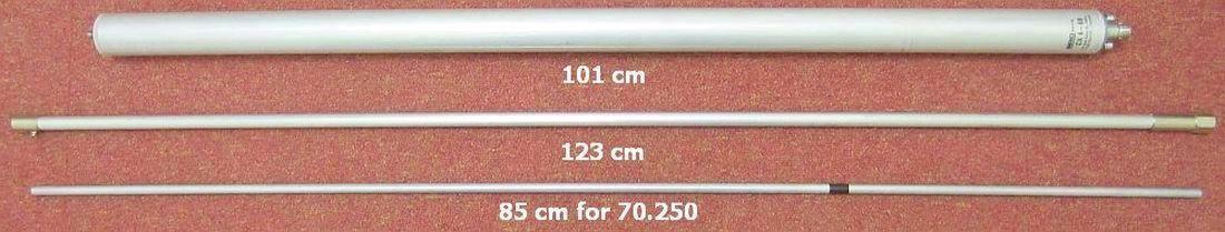
As a test, the antenna was set up on a 3 m pole and adjusted for the lowest SWR at 70.250 MHz. This was achieved with 85 cm length of the top rod.
The adjustment was done with a RigExpert AA-230 zoom analyzer. At least a SWR = 1.03 could be achieved on 70.250 MHz. The SWR at the beginning and end of the band was better than SWR = 1.2.
SEALING
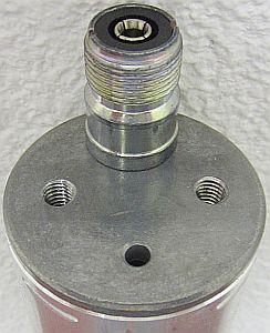
To prevent condensation water from squeezing between the bottom of the antenna and the mounting bracket, sealant was applied around the drain hole.
This also applies to the basis of the SO239 connector.
This measure forces the condensed water to disappear via the vent hole.
The black plastic bush around the antenna socket was glued to the bracket with kit so that a PL259 cable connector is protected against rainwater.
TO POSITION
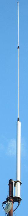

After making the antenna as waterproof as possible it was mounted on a 12 m high mast. The image shows that extra self-amalgamating tape has been applied at two points: the joint where the top vertical section of the antenna slides into the bottom vertical section and the joint where the bottom section is screwed on the hollow coaxcial section.
By installing at a higher mast, the capacitance compared to earth decreases and the antenna becomes electrically shorter so that the resonance increases.
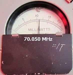
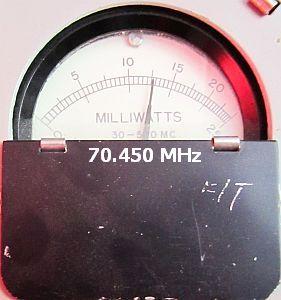
A vertical ½ wave dipole was used as a reference antenna in the attic and connected to a miliwatt meter. The power was measured at 70,050 MHz and 70,450 MHz. This is confirmed by the graphs of the Rigol and RigExpert analyzers.
NOTE: The antenna is tunable from 68 to 73 MHz. This can be done by sliding the top section in or out, but the gamma match tap remains unchanged. In fact, there is only one frequency where a correct SWR = 1 with 50 Ohm impedance can be found. At any other frequency, measured directly at the antenna or via a coaxial cable, the impedance will deviate slightly. An applied coaxial cable then acts as an impedance transformer so that the found SWR ≈ 1 with a different length ends up at a shifted resonance point.
REVIEW
The antenna is solid and robust in terms of mechanical construction. It is definitely worth its price (if treated as waterresistant).
It is a pity that the E-shaped mounting bracket is electrolytically galvanized instead of barrel zinc plating or made of stainless steel or aluminum.
It tunes really well within the 4 m band and the SWR at the band limits is below SWR = 1.2.
During two years in use, the resonance point shifts slightly during rain or very dry periods, but the SWR always remains < 1.04
That the resonance decreases in rain or damp weather can be explained by the fact that water on the antenna increases the capacitance relative to ground, which makes the system electrically longer.
In extremely hot weather, metal expands and you would expect that the resonance point of the longer antenna would also go down. However, the opposite is true and the resonance goes up and even falls outside the band limit allowed for us, but the SWR always remained smaller than SWR < 1.04. In fact, no difference with the first measurements in 2019!
![]()
