PA3GZK's WIDE BAND ACTIVE LOOP RECEIVING ANTENNA
![]() 06-mar-2021
06-mar-2021
WebSDR Weert (NL) use this active loop antenna.

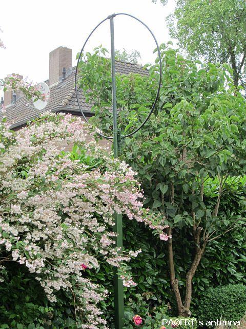
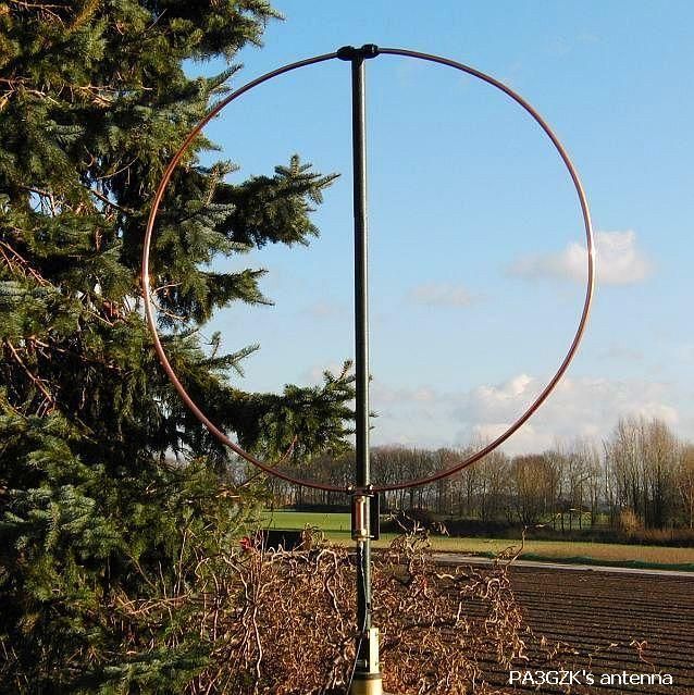
Left my green coloured loop as distinctive "bush" in my garden and on the right in PA3GZK's garden his trial model as described in this article.
INTRODUCTION

If one has no place for an antenna of sufficient length for receiving radio signals, a small active antenna may be the solution and you may find on the Internet a lot of related publications. If you want a system that is able to reduce or suppress interfering signals, most articles are not appropriate! The following design has that noise cancelling quality, you can confirm it by listen to MP3 files later in this article!
PA3GZK has built quite a number of active antennas in various forms and he experimented extensively. The antenna described here (fig ») gave by far the best performance and it was the final result of many tests with various circuits and systems. For a properly functioning antenna, and a substantial symmetry of the system, it is recommendable to follow the mechanical construction as well as possible.
For me, the reception decreased the interfering noise especially in reduced interference on the 160 and 80 m bands. Other hams have also found favour with the system. Someone about 16 kilometres away could not listen on 80 m, but he was a returned SWL with an antenna made PA3GZK.
Because in practice the antenna worked well with a current of 45 mA, I made a constant current source power supply. The current remains constant despite the length of the sypply line. In the unlikely event of a short circuit in the antenna or supply line, there is no insuperable damage!
See also: PA0FRI's active loop antenna.
DIAMETER LOOP = 120 cm
The proposed 120 cm diameter format is an in practice proven comprimise between desired signal and reduced interference. Large diameter, stronger signal, less aiming effect, small size, sharp aiming effect and less S points when receiving. Furthermore, with a larger model, more intermodulation products can be produced and a disturbing signal cannot be nulled well in the experience of the designer.
BTW: In other publications I have not yet found the recommended maximum size.
My experience is that the antenna should be set up at least 2 m above ground level.
GENERAL DESCRIPTION
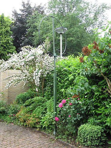
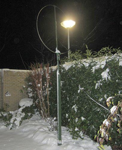
The shielded broadband (~200 MHz) active loop antenna offers more quiet and relatively less interference reception. It is known that an antenna for transmit also works well as a receiver antenna, one only forget that all interference signals are proportional strong. Therefore PA3GZK believe that you actually have to use two antennas, one for transmit and one for receive. The latter is most needed at the lower frequency bands.
This antenna is much less affected by fading (QSB) as a dipole or other similar antennas. The E-field in the near field that causes the most interference is very well suppressed, because the antenna within this field will primarily responsive to the H field. By turning the antenna the interference can be almost zero suppressed without losing the desired NVIS signal. With DX signals, there is a directional sensitivity established. Compared with a reference antenna the loop has a one S point decreased reception on average. A classic 80 meters Zepp antenna was used as reference at a height of 20 meters, while the loop was mounted on a 2 meters pipe. With active antenna the signal to noise ratio or signal to interference ratio was much better, listen to MP3 files in this article.
It showed that leaf touching the antenna has no appreciable negative impact on the operation, so hang or camouflage in a tree is not a problem.
The antenna is built with 15 mm soft copper tube and is designed as shielded symmetrical loop. This was done in order to minimise the disturbing influence of the surrounding conductive objects such as, trees, fences and gates, as far as possible. During testing with previous structures and models, it occurs that a slight disturbance of symmetrical construction affects the degree of noise suppression.
The active loop antenna can be installed close to a transmitting antenna without a problem. PA3GZK use the transmitting antenna 4 meter away from the receiving antenna, which is still intact despite sometimes 1 KW transmitter power.
RECORDING MP3 FILES
PA3GZK did the test with a Kenwood TS-480 tuned to the 80 meter band and the noise signal from a farm about 500 meters away. The recording is switched between a 80 meter Zepp antenna or a magnetic loop antenna having a diameter of 3.7 meters. The active loop antenna was rotated such that the interference signal was suppressed. The sequence was: the first 10 seconds Zepp - 10 sec. the big magnetic (transmitting) loop - 10 sec. Zepp - 10 sec. active loop - 10 sec. Zepp - at last active loop. Click on MP3-1.
The next test is about the difference between ZEPP and active antenna. PA3GZK switched several times between the two antennas. Click on MP3-2.
In this test, you will hear the difference if the active loop is directed or turned from the "jamming" source at about 500 meters distance. Click on MP3-3.
All tests run in the Dutch language.
IC INA-02186
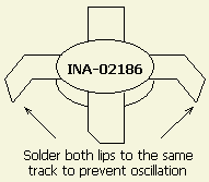
IC INA-02186 has now become "vintage" and readers mailed that more modern types are on the market. However, PA3GZK has experienced the successors are not as well resistant to overloading.
The IC is still offered via eBay.
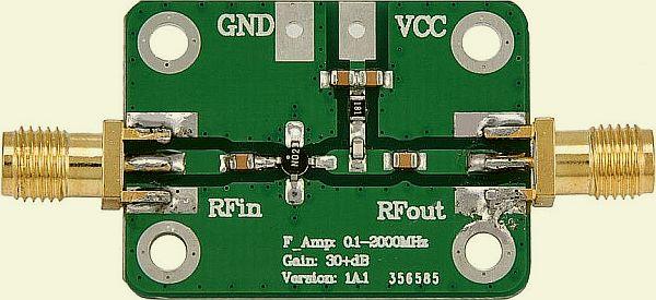
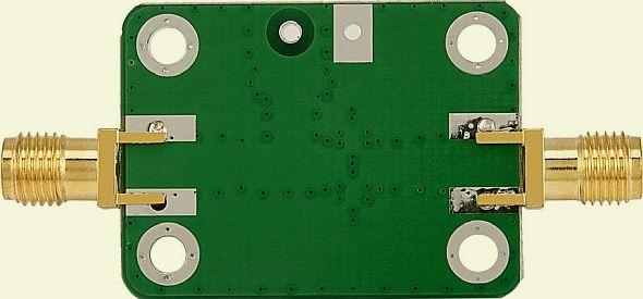

Dave Bunyan found on eBay a ready built amplifier board and when he looked closely at the photos of the MMIC on our board and compared it to the MMIC on the ready made board they both appear to be the same - the MMIC showing the number N02. He wrote: "The gain/frequency curve on eBay ad is identical to that on the INA-02186 datasheet. The complete PCB (5.2 × 2.4 cm) may be of interest to you and others who might want to try the loop. Adding the protection diodes and the 10 pF capacitor at the input and the 15 pf capacitor on the output should be easy to do. For powering up the coaxial cable an RF choke between the Vcc and the centre pin of the sma connector would work - I hope without instability - and SMA to F connector adapter for the output".
It has taken me a long time but I have finally got a working model of the shielded magnetic loop. It uses the board available from E-bay.
One important difference. I am using a 1÷1 balun wound on an BN-73-202 core. This is mounted on stripbroad and has a male sma PCB connector on it to make connection to the pre-amplifier easy. Results are very impressive - I cannot do a proper comparison - but I was listening to clear CW signals from DK1 and DF1 on Top band this evening. When I was G4XHN (1983-1988) I could not use top band it was so noisy. And I heard JK1P in QSO with a Portuguese station on 80 m. A short dipole fed through coax gives much poorer signals - but is all I had for short wave/medium waves.
The loop gives good signals in the LW broadcast band, without changing the input capacitors - which are 100nF - the same value in your circuit diagram. It works quite well in the FM Band - I will be testing it on 50 MHz and the 66-74 MHz Russian FM band when the Es season start.
The loop feeds an SDRPlay RSP and I have had to fit a 10dB attenuator before it. Without the attenuator there are inter-modulation products even with the gain turned right down and the LNA turned off.
Thank you for publishing the article.
David.
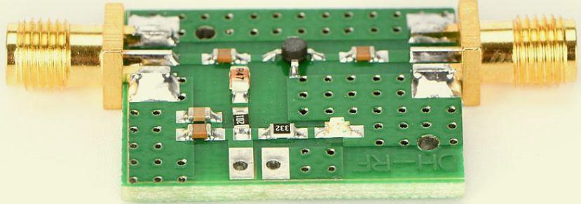
(PAØFRI) This PCB is from another supplier found on eBay.
I bought the following mini PCB via eBay, but it has not yet been tested. The imprint of the IC is filed and is most likely an INA-02186.
Features:
100% brand new and high quality
Specifications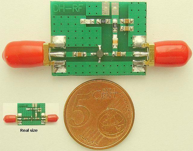
Size:25 × 52 mm
Diameter of end: 5 mm
Color:green + gold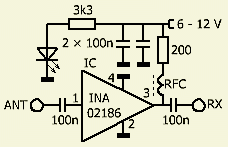
Operating frequency:0.1-2000 MHz
Amplifier gain:
F=0.1 MHz, gain=32 dB
F=500 Mhz, gain=31 dB
F=1000 MHz, gain=29 dB
F=1500 Mhz, gain=25 dB
F=2000 MHz, gain=20 dB
Maximum power output:+10 dBm (10mW)
Power supply voltage: 6-12 VDC
System impedance:50 Ω
Tips:
1.When working frequency is less than 600 MHZ,it get well gain flatness, can make it less than 1 dB after careful adjustment. The lower frequency the higher gain consistency.
2.Amplifier working frequency of the lower limit is subject to input and output capacitor, the default value is 0.1 uF, working to 0.1 MHz. Increase the input and output capacitance appropriately,can extend the cut-off frequency, such as 10uF capacitance can work to 5 KHz.
3.When the power supply voltage changes in 5-8 V, it can be used as a variable gain amplifier, gain increases with the increase of the power supply voltage, which suitable for radio frequency receive front-end circuit, using DA control power supply voltage, to control the gain of the amplifier, automatic gain control
4.When the power supply voltage in the 8-10 V, the low frequency end gain up to 30 db, at this time the amplifier has a low noise coefficient and good stability.
5.When the voltage is 12 V, reach maximum gain, the low frequency end gain of 32.5 dB
INTERMODULATION
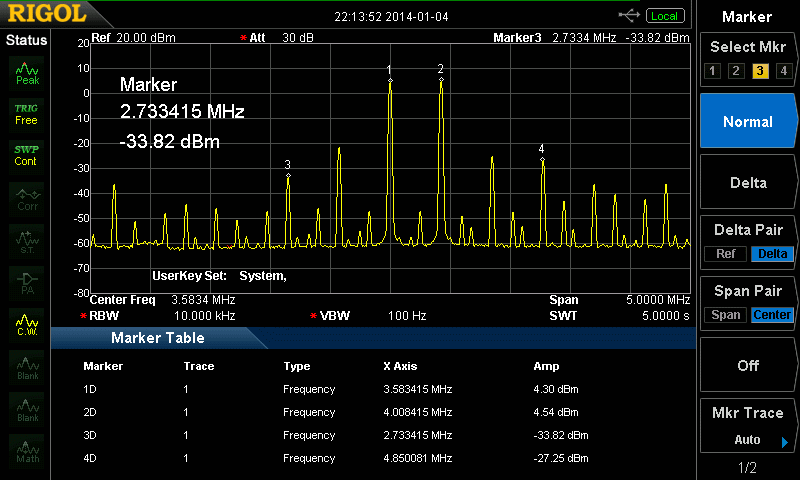
Marker 1D = 2 tone generator 3.58 MHz
Marker 2D = 2 tone generator 4 MHz
Marker 3D = intermod signal 3the order =-33 dBm
Marker 4D = intermod signal 3the order = -27 dBm
The generator level at the input of the amplifier was - 26 dBm (S9 + 50 dBm).
It is unlikely that such a strong signal is ever received by the antenna.
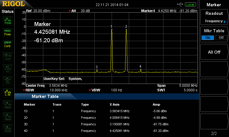
Marker 1D = 2 tone generator 3.58 MHz
Marker 2D = 2 tone generator 4 MHz
Marker 3D = intermod signal 3the order = -55 dBm
Marker 4D = intermod signal 3the order = - 55 dBm
The generator level at the input of the amplifier was - 36 dBm (S9 + 35 dBm).
It is evident that only a very strong signal is able to overdrive the amplifier.
MECHANICAL CONSTRUCTION
|
"HARDWARE" Soft copper tube 15 mm in length 4 meters. Brass T piece 15 × 22 × 15 cm compression fitting. Brass end cap 22 mm compression fitting. Copper tube 22 mm length 15 cm. Plastic T piece 15 × 15 × 15mm. PVC or polyester tube 32 mm length 160 cm. Trespa board 6 mm × 13 6 cm. Stainless steel threaded rod M6 4 nuts and washers. PL femail chassis connector The IC 02-186 INA is for sale at eBay.com The datasheet can be found at Alldatasheet.come |
Except IC and PL chassis one can obtain the other items in a regular hardware store.
For keen DIY's the following pictures will be clear enough to construct the antenna successfully. The previous design was build with a thick coaxial cable, but the present construction is easier to assemble, and the various mechanical components are standard.
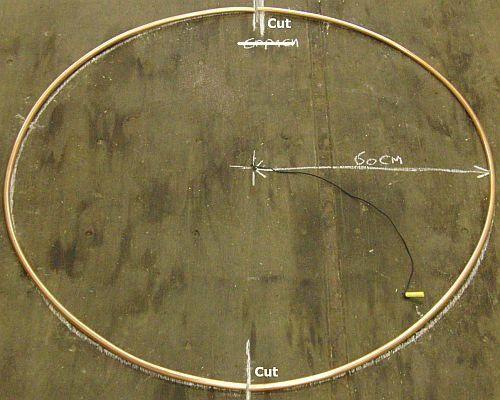
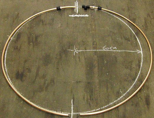
The 15 mm diameter soft copper tubing (from a hardware store) is 4 meters long, actually there are two easy to bend pieces of 2 meters.
The "bending track" is marked with a crayon and a piece of rope.

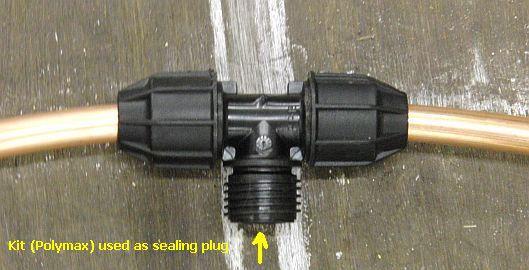
The plastic T connector, who is mounted on the standpipe, is sealed with suitable kit such as Polymax to avoid any water leakage or condensation.
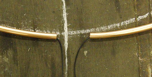
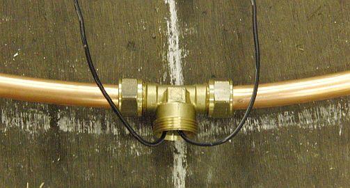
The flexible insulated wire does not need to be concentric.
|
|
|
|
Slide the amplifier in the 22 mm-copper tube. Solder the mass of the PCB with a suitable soldering iron on the inside of the tube. Also use that point for one side of the flexible wire. Solder the other side of the wire to the input of the amplifier.
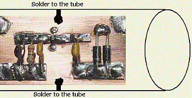
Solder both sides of the PCB to the («fig) inner side of the tube. Start with soldering thick wires to the tube and then solder pcb to the wires.
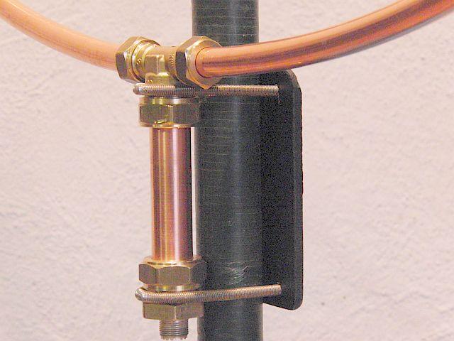
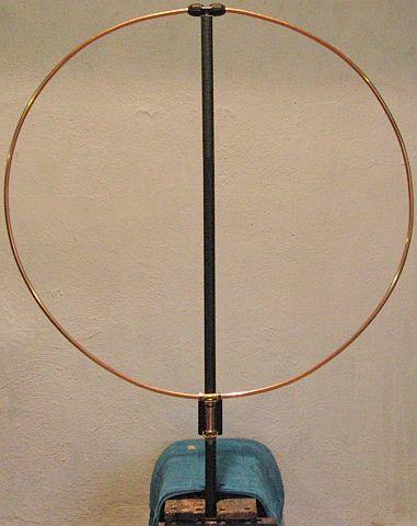
You may paint the antenna but oxidised copper does not affect the operation of the antenna
EMI/RFI

In previous models more components of plastics were used. The outer jacket of the coaxial cable worked as antenna for the transmitted signal and thereby upset the operation of the IC amplifier. In order to suppress a choke balun was installed. In the here presented model the choke is not been necessary. However if any instability occurs a cable suppressor may be used.
EXPERIENCE OTHERS
Hello,
Greetings from USA!
I built your antenna and I used the LNA from ebay. I didn’t follow the guide 100% because I was only able to buy 10 feet of 3/8 copper tube. But the results are amazing and it outperforms my PA0RDT miniwhip.
Thank you for your post.
G8JNJ
I like the neat construction method that uses 15mm copper pipe and irrigation pipe tees. But I thought that this is a very simple design would benefit from a more recent type of amplifier chip. The PGA-103+ would be a good candidate to try in place of the outdated INA-02186.
Tried a quick lash up using some RG58 test leads of odd lengths that were lying around to form a loop in the shack, and it works quite well. Especially considering it's sitting amongst all the PC's and noise generators. The loop size needs optimising, but I can already get quite good nulls and the loop isn't anywhere near properly balanced. I think it would work really well outside.
Although the antenna works to a certain extent there are a few problems.
The screened loop has several resonances within the required frequency range at around 4MHz, 20MHz and 40MHz which mess up the gain frequency response. It may be possible to shift these to less problematic frequencies by using an unscreened or smaller screened loop.
Another problem is that the PGA-103+ is designed for use as a wideband 'gain block' for use in 50 Ohm systems. However it's input impedance starts to rise at frequencies below 50MHz. So it's well suited for use in a 'voltage' probe E-Field antenna. But less suited for use as a 'magnetic' H-Field loop amplifier which needs to have a very low value of input impedance.
There is big mismatch between the loop impedance of low R high XC and 1K input impedance of the PGA-103+. It's possible to improve this by adding resistive damping to the PGA input, but it reduces the overall gain dramatically. I've also tried a 12.5 to 50 transformer which helps, but a lot of other equalisation would be required to get anything near an flat response curve. I suspect that this is likely to be a problem with the original design too.
Norton amplifiers have an input impedance of around 2 ohms whereas the PGA-103+ has an input impedance of around 1K ohm. So the PGA-103+ will work as a loop amplifier, but the mismatch loss means that the noise figure and gain flatness is not as good as it really needs to be for this application.
Loop amplifier designs by Chris Trask and Clifton Laboratories are good sources for further inspiration.
One further line of investigation is to use two PGA-103+'s to form a balanced amplifier. One connected at each end of the loop with their outputs combined via a 0/180 phase impedance transformer to 50 Ohms. A bit like the G8CQK simple active loop shown below.
I've also thought about putting the amp in a die-cast box and attaching the ends of the coax loop with something like 'F' or TNC connectors.
That way different size loops could be swapped as required or the loop could be easily broken down for portable / storage purposes.
GUUS
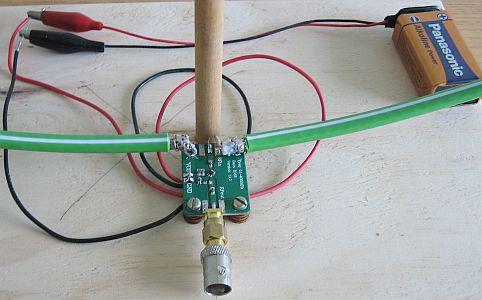
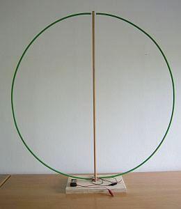
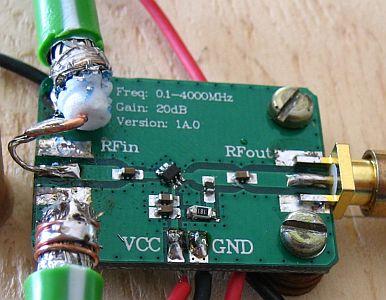
Guus, a visitor to my website, was encouraged to experiment with a mag loop. Coincidentally antenna installers in his neighborhood were busy with the installation of antennas. With a given lenght of green, fairly stiff coax (220 cm, diameter 70 cm), an experimental setup was made with an LNA (purchased via e-Bay, see photo above). It is not an INA-02186, but an SMD with 6 legs. Nothing was printed on and there was no documentation. Guus tested it with a voltage of 0 to 12 VDC and it worked well with 5 to 12 volts. For convenience, he used a 9 V block battery with a current rating of approximately 45 mA.
The result surprised him, because with a little turning of the loop the QRM in home or neighborhood could be turned away. In the end it worked better than his mini whip or some lenght of wire that unfortunately hangs inside. The test setup is simply on top of the receiver. Because it works so well, he is considering making a larger and more definitive active loop antenna. An 8-angle (such as PE1ADY) water pipe with an INA-02186 or equivalent amplifier plus a phantom feed. Everything can then installed outside or in the attic.

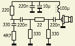 Other efforts were done with the INA02186 because sometimes instability occurred and the gain was too high.
A resistance at the input makes the load on the antenna more constant. A 220 ohm resistor in the power supply contributes to the stability and the impression exists that the noise level has decreased. Perhaps the amplifier oscillated slightly and caused the unwanted noise.
With the combination 330 pF and 4.7 Ohm the gain gradually decrease after 15 MHz and the resistors 47 and 150 Ohm further reduce the level, but this is my choice. If you want a different gain, you can that set with a 220 potentiometer. It is also possible with a "normal" attenuator.
HISTORY
Below is a selection of the experiments with this design.
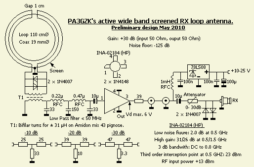
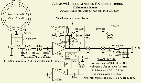
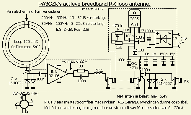
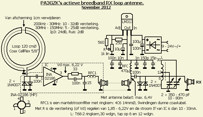
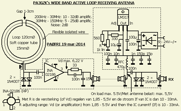
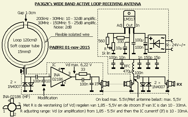
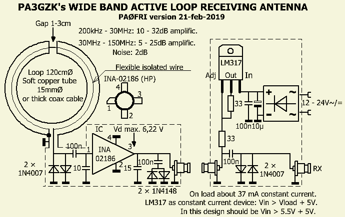
ASSEMBLING
The components are installed with the Manhattan system, ie the solder islands are glued PCB strips.
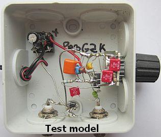
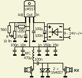
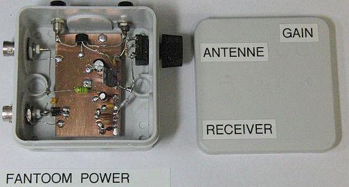
In previous schematic 330 ohm resistor was 240 ohm. Sometimes the IC was oscillating with short coaxial cable, therefore the resistance was increased and IC's supply voltage was reduced to 5.5 volts.
It will be clear that this supply is outdated by the simpler supply earlier in this article.


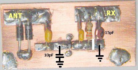
The INA 02186 has a high gain and a good connection to ground is essential. Some home brewers had to deal with an oscillating amplifier. To prevent instability ensure that both lips have direct contact with each other via one track. Do not separated by a machined groove, but solder on the same "island" or track.
POTMETER R
It turns out that adjusting R for the least noise is the best and not for maximum S-meter reading. Signal-to-noise ratio is then optimal.
Here the circuit is powered by 13.8 V. If the meter is turned too far, the system oscillates and a strong noise occurs. That stops when R is reduced again. My best result is achieved when R is set for about 30 mA from the 13.8 V power supply.
PA3GZK
The above information must be sufficient to DIY. In the extreme case of having a problem please contact PA3GZK via email: pa3gzk@amsat.org, but limit the email traffic as much as possible! He still receives questions that could have been prevented by reading the article carefully.