|
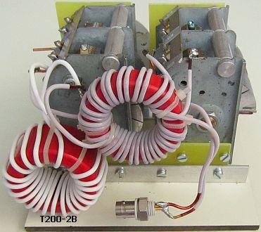
Testing the system with 2 × T200-2. |
|
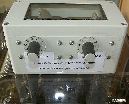
PAØFRI's TravelS-Match©
A SIMPLE SYMMETRIC HOLIDAY ANTENNA TUNER
|
Testing the system with 2 × T200-2. |
|
INTRODUCTION
This article contains a stripped 100 W tuner system that is mainly intended to match a holiday antenna. About forty years (since 1972) I have been experimenting and looking for a simple symmetrical antenna tuner. A lot of own designs and many other systems with up to two coils and two capacitors were tested in practice. Prior to this holiday tuner arose gradually a FRI-Match and a S-Match antenna tuner. Read if necessary, the relevant articles on my homepage. A combination of the two antenna tuners is the result that was long sought.
TravelS-Match©
The type designation for the tuner is TravelS-Match. According to Google's other names already proved to exist.
UNIVERSAL SYSTEM
More options.
Depending on the type of antenna an open line can be connected parallel across coil (L) or across the capacitor (C1). Frankly I must admit that the latter method is rarely used by me. It is also possible to match an end-fed antenna. As a result, it is a (limited) universal system!
The left figure shows (fig.1) that an existing Z-match optionally can be converted to the desired type. The right design (Fig.4) has not been tested. It will also work but two separate capacitors should be coupled via an insulating shaft, a real disadvantage.
MATCHING RANGE (10 BANDS?)
The design is actually designed for 10 to 80 meters including the WARC bands. The matching range is dependent on the antenna system, minimum and maximum capacitance of the two twin variable capacitors, and the manner in which the windings of the toroid are distributed. Therefore not always an equivalent result can be obtained, but it is usually sufficient for a holiday antenna like G5RV or something similar.
Unexpectedly the tuner matches my current 2 × 17 m antenna («fig) also at 160 m. However, with less power because the narrow plate spacing of the 2 × 470 pF capacitors. At 40 m the best result was with the open line across capacitor (C1). With this antenna, it was also possible to match the 50 MHz band for SWR = 1. A friend 16 km away noticed little difference with a 50 MHz vertical antenna that I usually use. Even an unexpected bonus, but in your situation it may work differently!
If no resonance is obtained another setting of the capacitors should be tried. Especially the 20 and 40 m bands may be critical. It is often a matter of a few degrees of the shaft and a vernier control is strongly recommended. It is possible that two resonance points occur, chooses the setting with maximum antenna current. Always match for SWR = 1, because it promotes the symmetry of the tuner.
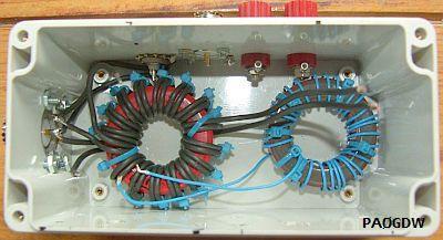
VARIABELE TWIN CAPACITORS
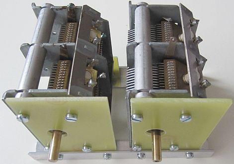
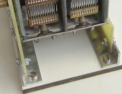
My method to isolate 2 × 470 pF capacitors (ex AM radio) from mass.
Two twin variable capacitors (2 × 470 pF) are used. They must be isolated from mass. The sections of one are connected in parallel (Fig.2) in order to increase the capacitance for an extended matching range. They can be in series (Fig.3) in order to increase the operating voltage.
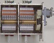
The («fig) plate spacing of present smaller types (2 × ± 330 pF) from portable transistor radios limited use to QRP. In general, in this application they are suitable for 10 - 80 m. It may be necessary to provide additional capacitance in parallel, or the number of turns of coil L should be increased according to the formula in the next subject. Fewer problems have one with the larger types as was used in vintage AM radios.
25 W QRP ATU
|
|
|
At first PAØGDW mailed that he build the design. He had two small twin 2 × 450 pF variable capacitors, all other components and a used ABS box in stock. So the construction was not an obstacle as a preparation for a future Elecraft KX3 12 W QRP tansceiver. The ATU was tested immediately with a 2 × 20 m dipole and 13 m open line. It worked perfectly from 20 to 160 m, but arcing with 30 W power due to small plate spacing. His ATU is actually a 25 W QRP Travels-Match.
TOROID COIL
|
|
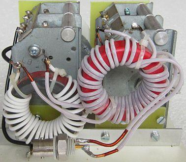
Coils with 15 turns , tap at 6 turns. For both toroid as coils applies: tap = 2n (turns) ÷ 5. n is the number of coil's maximum turns. |
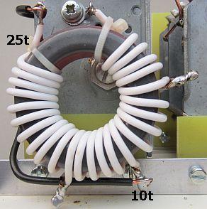
In stead of an air coil a T200-2 toroid is used to minimise the size (aeroplane luggage). Total 25 turns with a tap at 10 turns. You see more taps on the picture because the toroid was temporarily removed from a FRI-match. The inductance must be 8 to 10 μH. For the determination of the windings I used my own formula:
Tap = 2n ÷ 5 [tap = 2 × maximum turns (n) devided by 5].
You can still opt for an air-wound coil. As an example, the dimensions of two copies are shown.
BALUN
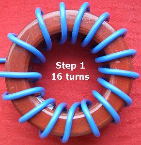
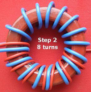
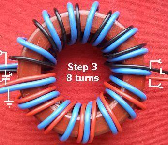
After the appearance of my S-Match publication, several comments on the Internet have appeared about the type of toroid and the manner in which the windings of the toroid are distributed. It is claimed one should use a balun with a ferrite toroid in stead of powder-iron types. So far I have not a suitable ferrite toroid that that stays cool with considerable transmitting power. So I keep to my original and proven design with a red coloured T200-2 iron powder toroid from Amidon/Micrometals. A step by step method for the windings is shown in the above pictures.
WIRE
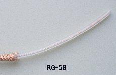
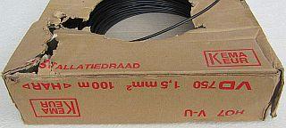
Preferably I wind the coils with Teflon insulated wire. Decades ago I tested installation wire, which get hot when placed in a microwave. A sign that it was not suitable for HF. The present installation wire has apparently not that useless feature. Black 1.5 mm² copper wire can be used in this design with 100 W power. One can (fig ») stripp off RG-58 or RG-59 coax cable so that only the inner conductor with insulation remains.
T200-2B TOROID
|
|
Test with a T200-2B type. |
If you think a T200 is too small, you may use a double-thick type T200-2B. The number of windings (fig») is used in the diagram.
EXPERIMENT WITH ONE TOROID
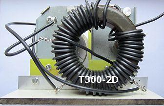
Both systems did not meet the expectations!
To further simplify the tuner I experimented with only one toroid. For sufficient inductance and more space for the windings, I opted for the larger and thicker type T300-2D. The core was equipped with 32 turns, taps at 6, 14 and 26 turns. For the coupling I used 12 turns or 2 × 6 turns. Unfortunately the experiment did not meet the expectation and the investigation was not pursued because the original idea worked well.
![]()