SIMPLE SYMMETRIC ANTENNA TUNER
(Especially suited for QRP or vacation)
VARIOUS OPTIONS
Capacitor and rolling inductor in an antenna tuner is structurally not symmetrical and may influence the balance of an antenna system. A simple symmetrical antenna system tuner with good performance is showed in the following schematic. One thinks nothing special, but the trick is in the correct connection of the components.
Fig. 1.
The terminals of a capacitor's rotor and stator may be interchanged as well as the "ground" terminal and shorting slider of the inductor. Despite the simplicity of the circuit (fig.1) a good symmetry was reached. For example in fig.a best result was obtained with the hot terminal of transformer's secondary connected to the "normal" terminal of the inductor. The slider and short-circuit contact of inductor was connected to the frame or stator of the capacitor. More combinations are possible but in terms of symmetry the shown circuits were the best.
THE BEST SYSTEM
Of these four selected tuners the model fig.e had the best symmetric properties. That's practical because one want to match 50 Ω to an random antenna. In fact, this is a universal tuner as input and output are galvanic isolated.
Therefore it does not matter what kind of impedance you want to match e.g. coaxial cable, open wire line or antenna. If the tuner is mounted in a metal box install the components at a proper distance, 5 cm or more from the metal parts.
However the ATU of fig.b («fig) works with most antenna systems.
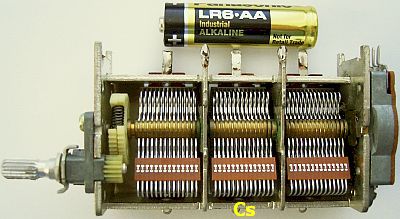
In many antenna systems a 22 μH rolling inductor and 500 pF capacitor are sufficient to match from 10 to 80 meters. Increase the value of inductor and capacitor for 160 meters. For maximum symmetry try to obtain as lowest SWR (=1) as possible as this detail is essential!
ISOLATING TRANSFORMER 3 to 5 μH
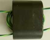
The isolation transformer (fig.2) should be wound like an («fig) input or output transformer of a transistor PA. Spread the windings evenly on the toroid. Between primary and secondary windings may exist a high voltage, so it is wise to use good (Teflon) insulation. Not all ferrite's compositions are suitable in this application, but one may use toroid types as FT240-61 and 4C65. I did not try the latter types and stick to the iron powder toroids. An Amidon/MicroMetals T200-2 type is suited for maximum 800 W output. For more power glue two of more toroids together or purchase a larger T200A-2 type. For QRP you may use a smaller one but I recommend the larger ones because the more available space for the windings. A suitable inductance for both primary and secondary coils is 3 to 5 μH.
COIL WITH TAPS
If a roller inductor is not available but a coil with taps, mount («fig) an additional variable capacitor (Cs) of at least 500 pF at the primary coil between the cold side and ground. This is for fine-tuning of the system. Due to lower RF voltage at this point, the plate distance of the capacitor's plates can be narrow. So a smaller (fig») variable capacitor is suitable.
This second capacitor reduces the efficiency of the tuner but that is in practice irrelevant because it is hardly noticeable.
UNIVERSAL SYSTEEM
|
|
The principle. |
|
Earlier in this article it was showed that two systems were required for upward or downward transformation where only one type (fig.a) stands out for the best symmetry. Both types ATU can be brought together in a universal model (fig.c) with a step down input transformer 4 : 1 (50 : 12.5 Ω). The antenna tuner becomes simpler and smaller, a benefit for (QRP) stations on vacation.
There are also some disadvantages because the variable capacitor will have a greater capacitance and the zero capacitance can be too much in the upper frequency range. With some antenna systems the efficiency of this ATU is less than the fig.a type.
IMPROVEMENT
When the ATU is made, it is for best symmetry worthwhile to interchange the terminals at the input or (and) at the output of the transformer.
![]()
![]()